Hi everyone,
Having successfully built the design linked by Gabriel (you’re the man !), I am trying to iterate on it and replace the hobby-grade probes (which are not designed to be permanently immersed) with industrial-grade probes. I have ordered two probes from a Chinese manufacturer which unfortunately came without instructions or technical documentation.
I have:
a RS485 based pH probe
an analog EC sensor
To connect those, I have:
a UART device to translate from RS485 to USB
an ADS1115 to translate the analog signal
I am trying to figure out the wiring of the probes. I am admittedly bit out of my depth and would love if someone more experienced could help here. This is part of a bigger project to use mycodo to automate a greenhouse in a low-income country context, and I am more than happy to share all the blueprints, contribute to the github, etc. to showcase how impact mycodo can be.
Specifically on the wiring:
the RS485 pH probe has 5 wires: shield, 2 temp, negative and positive
the analog EC probe has 4 wires: 2 temp, 2 for measuring.
Two questions:
is this enough information to go on to know how to connect the probes?
if yes, how should I connect them?
if not, what additional information should request from the manufacturer?
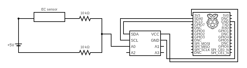
An update – I have been able to read the current from the sensor. I now need to convert the current signal into an analog signal for the ADC. This is the set up I have right now - any advice on how to convert the variable current coming from the sensor into a variable voltage for the ADC?
Bart, I’m building a somewhat similar circuit as the one above also using an A to D. For test, I believe one can replace the EC Sensor with a 1K resistor and that should give a reading of 1000uS assuming the sensor has a K=1.
I’m guessing from the diagram you are using an ADS1115 for the A to D. That part has an absolute max input voltage equal to Vcc which you show to be 3.3VDC. So it would probably be better and safer to replace the 5VDC supply with 3.3VDC. The resistors will need to be adjusted to get a reasonable voltage range at the input of the A to D.
I would also like to point out that exciting a simple probe with DC will polarize the nutrient fairly quickly and give erroneous results.
Super helpful, thanks.
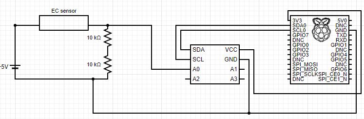
I’ve changed the wiring slightly - below is the current one - and I’ve been able to get readings although there are in a very narrow range. I might look at using an amplifier to increase the signal to utilize a larger voltage range.
Veng1: Thanks for the input on the AC vs. DC. Previously, I used Gabriel’s wiring diagrams where the probes were supplied power from the RPi. Does the RPi provides DC power? If yes, would the sensor have the same issue that you mentioned?
I guess I should ask if the block you have labeled “EC sensor” is a probe or an assembly with a built in processing circuit?
I was assuming you just meant it is a probe. If so, the circuit probably doesn’t need two 10k resistors. One should be enough and even it may be too large. With one 10k, your range should double. Be careful that the input to the A to D doesn’t exceed Vcc (3.3V).
It is just the probe - it does not have a transmitter or any other circuit that I can see. This is the link to the probe - no data sheet available unfortunately, which is why I’m fumbling my way forward.
I’ll try with one 10K resistor, however with Ohm’s V = IR shouldn’t voltage reduce if I decrease the resistance value?
One way of debugging your set-up is to change the input to the generic A to D which should allow you to read just plain voltage. That probe has a K=10, so it is designed for higher concentrations that I normally see in hydroponics but that doesn’t mean it won’t work.
If you really need a reading of 20,000us, then that says the sensor should have an equivalent resistance of 50 Ohms. I would not recommend starting there. Rather, replace the sensor with a 1k resistor and see if the circuit is actually working.
The equation that guides is:
Vat_input = Vcc*(Rsensor/(Rsensor+10k))