Grove I2C Motor driver support

Bought a couple of seeed studio I2C motor controllers. They are super cheap and I want to keep everything connected to the I2C bus for wiring simplicity.

Never really coded in python, so we will see how it goes. It looks fairly simple to make the motor run looking at this guide , so I’ll give it a shot mashing it together with the generic pump module.

Each module are designed for running 2 dc motors, but in reality it can run 4, as peristalic dosing pumps aren’t run in reverse.

1 Like

That looks like a nice board. I’d recommend copying either the stepper motor Output or the DC motor Output to get started. They’re likely to already have relevant user inputs/settings for this board.

Also, can we acknowledge the early 2000s Angelfire/Geocities vibe that tutorial page puts off:

1 Like

That and how cool does Japanese commenting look. Have to make sure to keep the comments from whatever I reuse from the example

I actually just added support for reverse operation for the Atlas pump Output. There are dosing setups that would need reverse operation. For instance, I designed (but never constructed) a multiple solution dosing system that used only one pump and a series of valves that determined which solution was being drawn from. Reverse was necessary in order to back-pump and clear the line of chemical back into the originating container before starting to pump from the next container.

I’ll try and make the output with two motors first similar to the existing motor driver and then a separate 4 motor version

As I said. I know little to none about python, but I manage to get mycodo to digest the file. I think I have made it all the way to class OutputModule, so now on to actually figuring out how to make it shoot out I2C bytes:) Ill and copy some stuff from the grove relay output.

Question: I want to be able to change the name of the channel so its not just Motor A and Motor B. I have created the input field for it, but not sure how to override the standard “name”

channels_dict = {
    0: {
        'name': 'Motor A',
        'types': ['volume', 'on_off'],
        'measurements': [0, 1]
    },
    1: {
        'name': 'Motor B',
        'types': ['volume', 'on_off'],
        'measurements': [2, 3]
    }
}

Grove I2C Motor controller.py (11.1 KB)

You need to create a text input with the id “name” under custom_channel_options. See grove_multichannel_relay.py for this in use:

He. I already did that. It works, I must have forgotten to test the latest one I created.

Before burring myself to deep in it, is there a reason to assume that copying most of the output module from the multi channel relay and adapting it wouldn’t work?

You will want to duplicate a module that is most similar to the one you want to build in order to minimize the changes that will be required to get it working with your hardware. It would seem another DC motor controller module would be what you’re looking for. I merely mentioned the multi-channel relay module for that excerpt about the “name” custom channel option.

Just came across a recent post on the old forum that includes a Grove I2C Output module and wanted to link it here.

Yaaah. Less work for me.

I think I came across that post some time ago before I started this project. I just forgot it:)

Here’s a slightly modified version of the Output module from the old forum post. Could you please test and let me know if there are any issues? If everything works, I’ll add it to Mycodo. You can import it on the Configure → Custom Outputs page.

Module Test 01: grove_motor_driver_v1_3_01.py (16.4 KB)

Hmm, not really. I can see the board on the address I entered but nothing is working. I have these unconfigured.

Anyhow, looking through the code it seems to be a different byte set than in the library for my board. Apparantly the different I2C grove motor drivers doesnt work the same way. Ill try and adjust the code and see if I can get it to work.

#define GROVE_MOTOR_DRIVER_DEFAULT_I2C_ADDR 0x14
#define GROVE_MOTOR_DRIVER_I2C_CMD_BRAKE 0x00
#define GROVE_MOTOR_DRIVER_I2C_CMD_STOP 0x01
#define GROVE_MOTOR_DRIVER_I2C_CMD_CW 0x02
#define GROVE_MOTOR_DRIVER_I2C_CMD_CCW 0x03
#define GROVE_MOTOR_DRIVER_I2C_CMD_STANDBY 0x04
#define GROVE_MOTOR_DRIVER_I2C_CMD_NOT_STANDBY 0x05
#define GROVE_MOTOR_DRIVER_I2C_CMD_STEPPER_RUN 0x06
#define GROVE_MOTOR_DRIVER_I2C_CMD_STEPPER_STOP 0x07
#define GROVE_MOTOR_DRIVER_I2C_CMD_STEPPER_KEEP_RUN 0x08
#define GROVE_MOTOR_DRIVER_I2C_CMD_SET_ADDR 0x11

What does this mean?

What board version do you have? The module, above, was designed for board v1.3.

I see in the photos from the link it has “1.0” printed on the board. Is this the version you received? If so, you will likely have to develop your own module that’s compatible.

Hey there. I am the poster from the previous forum working on the Grove I2C Motor Drivers. I got it working pretty well, at least going at one calibrated speed. I took my test setup down and got working on some other stuff in the mean time. Happy to help if I can

You may still have some issues as you guys have pointed out because this is the exact board I bought. Which is a different version than what you linked

1 Like

Thx.

Its not a different version of the same board, but a different board altogether. I just wonder why they would make different command sets for each one:) With the example provided I hope its straight forward getting it to work.

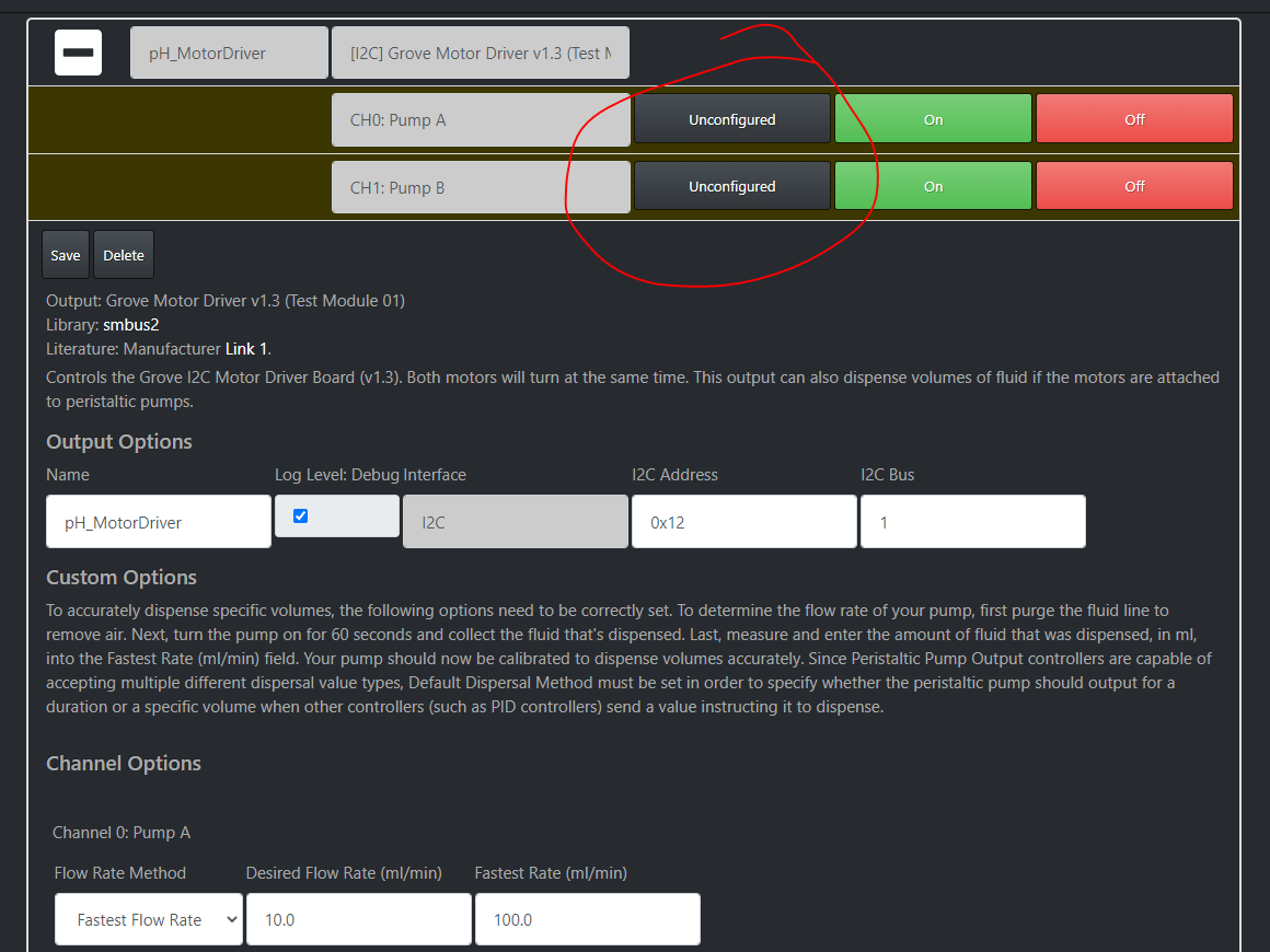
Looking at the example, im not sure I understand how the different channels are tricked. Looking at the code it seems like its adjusting both channels at the same time. For instance:

        if state == 'off':
            if self.currently_dispensing:
                self.currently_dispensing = False
            self.logger.debug("Output turned off")
            self.motor.motor_speed_set_a_b(0, 0)

Or

elif state == 'on' and output_type == 'sec':
            if self.currently_dispensing:
                self.logger.debug(
                    "Pump instructed to turn on while it's already dispensing. "
                    "Overriding current dispense with new instruction.")
            self.logger.debug("Output turned on {}".format(direction))
            self.motor.motor_speed_set_a_b(100, 100)
            if amount > 0:
                self.motor.motor_direction_set("cw")
            elif amount < 0:
                self.motor.motor_direction_set("ccw")

The reason I ask is because my board triggers each channel individuel. This drives the motor(s) in the current version

def motor_direction_set(self, direction):
        """Set motor direction, either cw or ccw"""
        if direction == "cw":
            direction_address = 0b1010
        elif direction == "ccw":
            direction_address = 0b1001
        else:
            return

        self.bus.write_i2c_block_data(
            int(str(self.i2c_address), 16),
            self.DirectionSet,
            [direction_address, 0])
        time.sleep(0.02)

In my version this drives the motors

def motor_run(self, motor_channel, speed):
        """Set motor speed"""
        speed = self.map_vals(speed, 0, 100, 0, 255)

        self.bus.write_i2c_block_data(
            int(str(self.i2c_address), 16),
            self.speed,
            self.GROVE_MOTOR_DRIVER_I2C_CMD_CW, #I know it only runs one way at the moment:)
            [motor_channel, speed])
        time.sleep(0.02)    
        # I2Cdev::writeBytes(_addr, _buffer[0], 2, _buffer + 1);

The last line is from the arduino library. Im a little unsure on how it differs with the pi

Yaaah. I made a motor run, but it wont stop:) I Tried both the stop and brake address. Both should work

def motor_brake(self, motor_channel):
        """Set motor speed"""
        self.bus.write_i2c_block_data(
            int(str(self.i2c_address), 16),
            self.GROVE_MOTOR_DRIVER_I2C_CMD_STOP,
            motor_channel)

        time.sleep(0.02)    

        #     I2Cdev::writeByte(_addr, GROVE_MOTOR_DRIVER_I2C_CMD_BRAKE, chl);
        #     the chl is a integer

grove_motor_driver_v1_3_01.py (16.9 KB)

I would not rely on the v1.3 board library to determine appropriate code for the 1.0 board. You’re likely to find multiple issues. It’s probably best to find Python code designed for the v1.0 board to work with.