Hello,
I am trying to replicate Automated Hydroponic System Build. However, I am having difficulty understanding what all of the three circuitry parts do that I circled in the image in red. Specifically, does the black wire that connects to the raspberry pi on the right side of the image go into an outlet or computer; in other words, how does the rasberry pi communicate with the mycodo code? Also, how does the power box work and where is it connected. Moreover, what does the bottom three circuit components do? Also, how can I add LED light strips (Amazon.com) and a water flow meter (https://www.amazon.com/DIGITEN-Effect-Sensor-Flowmeter-Counter/dp/B01EA3C6LS) to the hydroponic system circuitry? Thank you for your time and assistance!
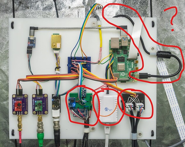
This is the power cord.
Mycodo is installed and runs on the Raspberry Pi. The operating system and software is located on its micro SD card.
The power box simply has 4 relays controlled by 4 GPIO pins that, when set high, will switch each relay they’re connected to. Each relay is connected to an electrical outlet, which enables controlling power to any device connected to each outlet.
Left: I2C temperature/humidity sensor, I2C flow meter circuit (measures water flow), I2C analog-to-digital converter (measures voltage from a current-sensing transformer), simple switch to measure the reservoir float sensor.
Middle: Ethernet box used to transmit 6 pins connected from the Pi to the Outlet Box: 4 GPIO (one for each relay), ground, and 5 volts.
Right: Ground, 5 volts, SDA, SCL (I2C) are broken out on a breadboard to 4 Atlas Scientific peristaltic pump wires.
Controlling powered devices (e.g. lights) can be done simply with a relay, of which there are many documented methods. As far as water flow meters, they typically operate the same way, but if you’re not using the hardware I’ve documented (Atlas Scientific circuit board and flow meter), you’re going to have to refer to other documentation to understand and get it working.
1 Like
