Hi there, I’ve been working on setting up a mushroom growspace using Mycodo as the controller,
Using on/off GPIO I’ve managed to get my 4 relay board to switch powersockets on or off allowing me to run fans/humidifier/lights and Co2 sample pump.
But for my air circulation, I also have two servo driven 3d printed butterfly valves. I know it’s possible to set these servos without adding any hardware in between them and the raspberry pi, since when I run a script outside of Mycodo using:
“from gpiozero import AngularServo”
I can make the servos work, but I can’t for the life of me figure out how to get Mycodo to move the servos. I don’t really want to add an i2c solution in between, since running power to it is a bit of a design nightmare.
Can someone help me out? I think the way forward is to make a custom output script, but I haven’t been able to get that to work.
If it helps, I’m using MG90S servos (though most likely counterfeit ones)
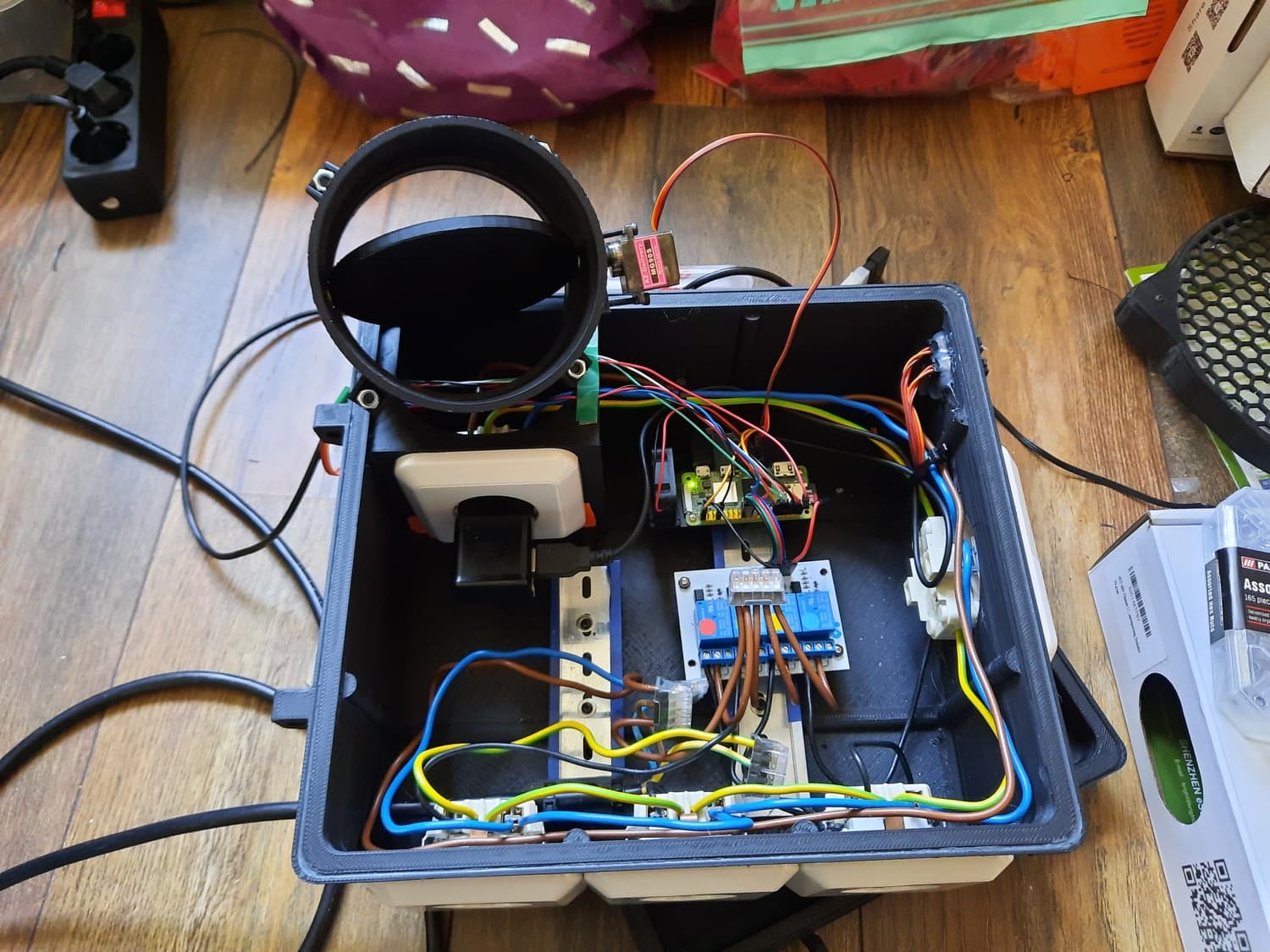
Finally, allow me to share a picture of my mycodo utility box.
Are you powering those servos directly from the Raspberry Pi GPIO? If so this is dangerous as it could easily draw too much current from the GPIO and permanently damage the Pi. You should be powering devices separately with their own dedicated power supply, and only sending control signals to the servos from the Pi.
As far as I know, there is currently no support in Mycodo specifically for controlling servos. However, servos use PWM for control, and there is a PWM Output module in Mycodo you should be able to use…
You can also control PWM duty cycle from within a Function using the PWM Action…
You will need to do some testing and tinkering to get the servo to turn to the desired angle. You could also write a custom Conditional Controller using Python.
You will need to get the operating parameters of the servo from the manufacturer… specifically what the PWM frequency needs to be set to and also the pulse timing (in milliseconds) for the specific angle you want the servo to reach.
The other alternative is to do away with the servo-controlled butterfly valve and just power the fan on or off instead of opening a valve. Or use a simple flapper valve on the air inlet that opens under air pressure when the fan turns on.
the action to set a duty cycle would be for later, right now I can’t even get the servo to respond to the duty cycle in the first place.
I’ll have to consider the safety of the Pi a little, I do recall reading that a resistor between the Pi and the servo isn’t a bad idea.
edit: reading a little more it does look like I wont be able to avoid doing some redesign of how I power the pi and peripherals… guess I need to get rid of the 5v 2a phone charger currently powering everything and put in a barrel jack somewhere.
I’ve tried backdraft dampers, but I felt like the fans I was using only barely manage to push those open, I really want to do all I can to contain the humidity and potential spore rich air within the grow space. so the butterfly valves were the solution.
You really should never power any kind of high inductance load directly from the Raspberry Pi GPIO pins, ever. This means any kind of coil… motors, heating elements, servos, relays, etc. Also, when a coil is de-energized, the collapsing field creates a reverse voltage spike which might damage the Pi if no protection circuitry is in place. It’s just simpler and safer to have separate PSUs for all of your peripherals and a dedicated PSU for the Pi to help isolate any EMI as well. The only thing you should really power directly from the Pi GPIO are your i2c or SPI sensors.
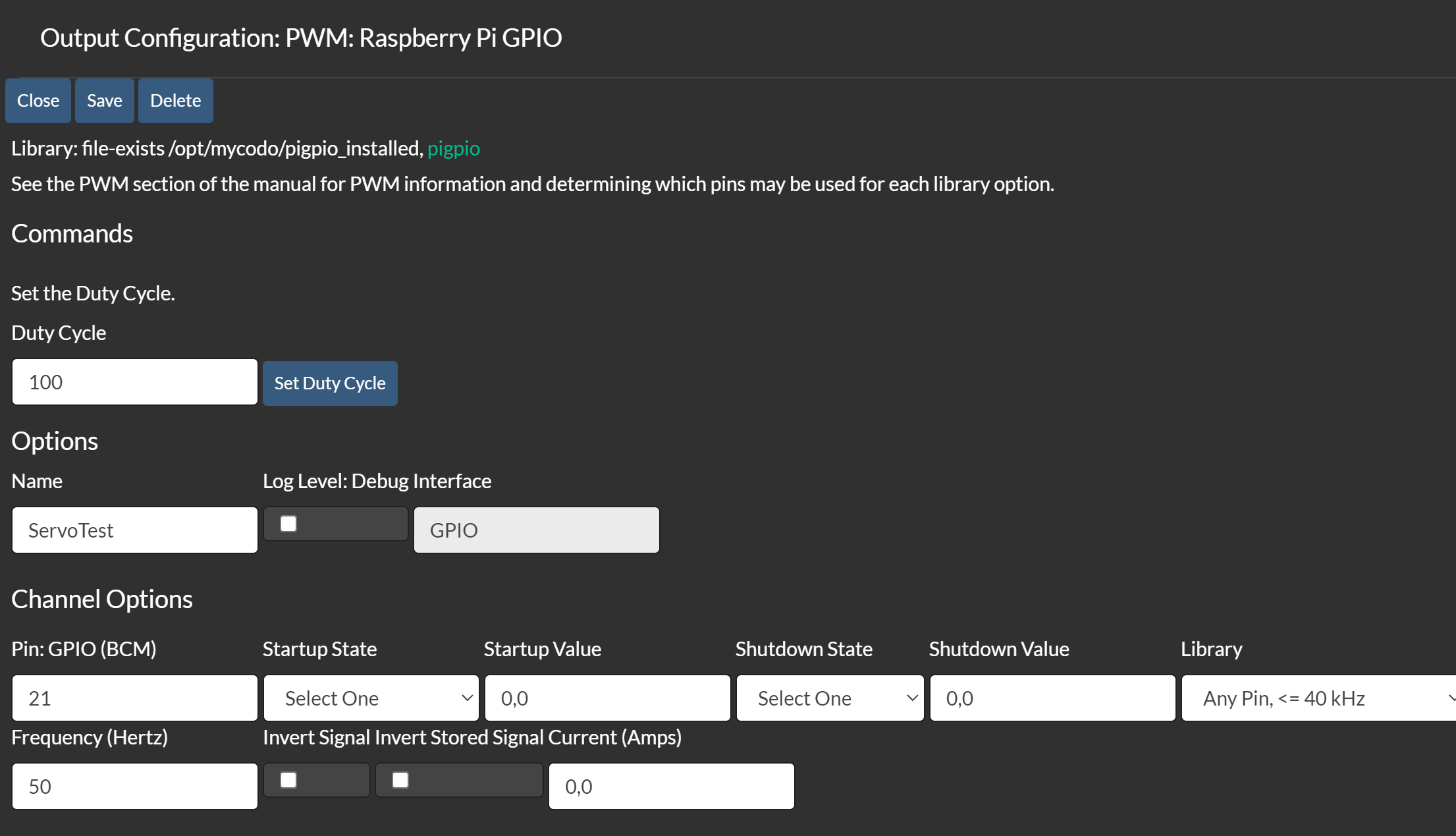
In your PWM setup, set the startup state to ON and save the settings.
Then try manually setting the PWM duty cycle by incrementally changing the Startup Value one at a time, starting at 0 and working your way up, and clicking save on the settings after each change. You should eventually get some kind of response from the servo.
What you really need to know is what the microsecond-timing specs are for that servo. Usually the manufacturer will have specs that tell you what microsecond-timing = min, idle, and max travel on the servo. Then you need to convert that microsecond-timing into PWM duty cycle to figure out where the servo’s control-band is. This kind of explains it a bit…
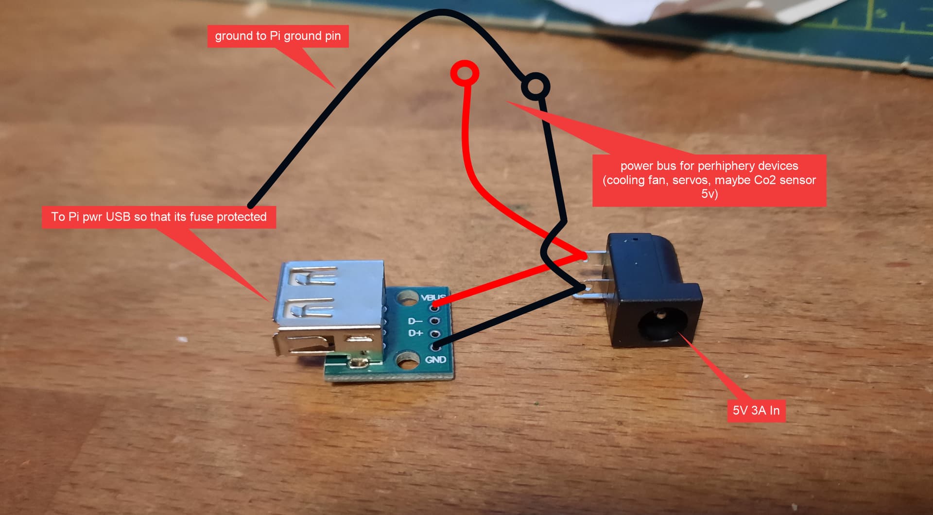
This is the current plan to provide a separated power supply to the coiled devices btw.
The problem is that I only designed for 1 internal 220V socket. but I think like this the Pi is protected by the fuse and I still have access to more A than the fuse will allow for the coiled devices in the system.
Just figured I’d share it since you seem to have a solid grasp on what is a bad idea and not.