At the moment I’ve my rpi working with a few sensors, two cameras, two solid state relays and I would like to add two more relays. I’m worried about damaging the rpi by surprasing the maximum current draw from the GPIOs.
My questions are: How do you measure current draw from GPIOs? How many relays can handle a rpi in your experience? What do u recommend to handle more than 2 control signals?
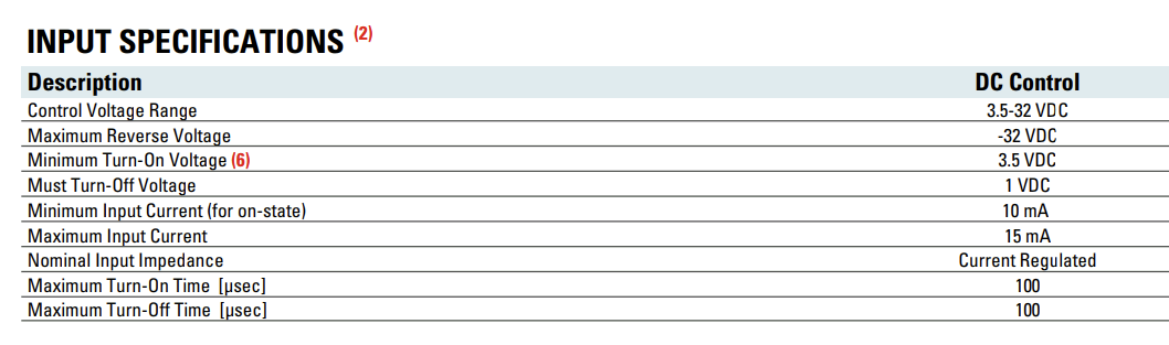
When wiring relays directly to the Pi, you should refer to the datasheet to find the current sunk on the switching side of the circuit. For instance, this Crydom D1D12 solid state relay (SSR) requires between 10 and 15 mA current on the input:
Since the Pi is rated at a maximum of 16 mA per pin and the total current from all pins not to exceed 50 mA, you could safely connect 3 of these SSRs (and maybe up to 5 without noticeable issue). You’ll need to refer to the documentation of whatever hardware you’re using to determine if it’s appropriate.
To expand the capabilities of Pi (or any single board computer), you could use GPIO expansion chips, such as the PCF8575 or MCP23017, among others. These put the SSR input load on the chip and not your Pi and typically can endure much higher maximum loads. For instance, the MCP23017 can source/sink 25 mA for any single pin, and has a combined total maximum of 150 mA for all pins.