Yes, I have seen CAN shields for Raspberry but they have all either been very expensive or only CAN 2.0b.
The SG Electronics ones are new to me and CAN FD for €45 is very reasonable!
Yes, I have seen CAN shields for Raspberry but they have all either been very expensive or only CAN 2.0b.
The SG Electronics ones are new to me and CAN FD for €45 is very reasonable!
For my relay use case maybe m4 feather is the way to go
Using a Pi Zero will make the entire experience painfully slow, even without using a webcam.
Replacing the Pi Zero 2W with a Pi 4 made a world of difference and saved my walls from any further forehead-related damage.
Yes, I have been painfully aware that the Pi Zero is too slow. I am actually using it in one setup but will replace it soon. The good news is that there are alternatives:
This looks really cool!
I saw that there’s currently revision 3 of the hardware. Would now be a good time to buy the hardware, or is there a new release/update soon?
Also - for the Raspberry Pi Zero performance thing - is there a reason you don’t use say, the Raspberry Pi CM4 or CM5 boards instead? Is it a cost thing? Or something else? (I did see your article on other SBCs - but I figured the Raspberry Pi CM would be the most well supported, and least headaches for everybody. But possibly I’m missing some context here).
Also - for the connectivity, the CAN FD is just for the connectivity between the main board, and the sensor boards, right?
I noticed a lot of commercial and industrial agricultural/greenhouse/grow-room sensors seem to standardise on using Modbus RTU (over RS-485) - e.g. soil sensors, PAR light sensors, temperature/humidity sensors, pH sensors, water pressure sensors, flow-rate sensors etc.
Do you think it would be feasible to add in support for connecting to a Modbus RTU (RS-485) network from your boards?
I saw that there’s currently revision 3 of the hardware. Would now be a good time to buy the hardware, or is there a new release/update soon?
The current workflow so far has been that after I order a batch of boards, I use some myself and sell the rest. Once all sold I gather the feedback, redesign and order the next batch. I currently have 2 more boards from the revision 3 and since I pay for this myself I want to sell all before starting the next revision.
Regarding if this is the right time or not depends on if there is anything specific from revision 4 that you require. R3 do not have any (known) major faults and are working fine. I use one myself. For the discussion about R4 you can find them here:
Also - for the Raspberry Pi Zero performance thing - is there a reason you don’t use say, the Raspberry Pi CM4 or CM5 boards instead?
The design of this board started before I even knew Mycodo existed. The design choice to include the header for RPI Zero was at the time that this board was very affordable, easily available and small enough to be integrated nicely. CM4/5 could have been a choice but would be somewhat harder to get started. For a simple python script to measure some sensors and switching a couple actuators then the power from a Zero would suffice. Then Mycodo came into the picture and showed me that a more powerful SBC was required.
This design choice has not been changed, mostly due to it would require a lot of work to integrate the CM modules instead to the board. An easier approach would be to make an adapter board with CM4/5 on top and the 40-pin connector on the bottom to RootMaster. This is still an option but I have not had the opportunity to experiment with this myself yet.
Do you think it would be feasible to add in support for connecting to a Modbus RTU (RS-485) network from your boards?
This is news to me, I have not seen many of these sensors before. Perhaps because I am too new to this. Since my project is modular I think a good approach is to make a daughter board with RS-485 and CANbus that can extend the network with this functionality. This is a good way to start experimenting first and see how well it fits before doing any more integrations into the main board. What do you think?
EDIT: Sorry, hit save too soon!
Thanks for the info about revision 4 =).
I’d definitely be up for buying a couple of the boards - maybe 3-4 of your boards if I can stretch? (including 3D printed cases) However, I’d definitely like to see if it could use say, a CM5 out of the box. I think it’s a more common SBC, versus some of the other options (and so would might have more support from other projects/code/drivers etc.)
Is the footprint an issue with the Raspberry Pi CM5 vs Pi Zero W2?
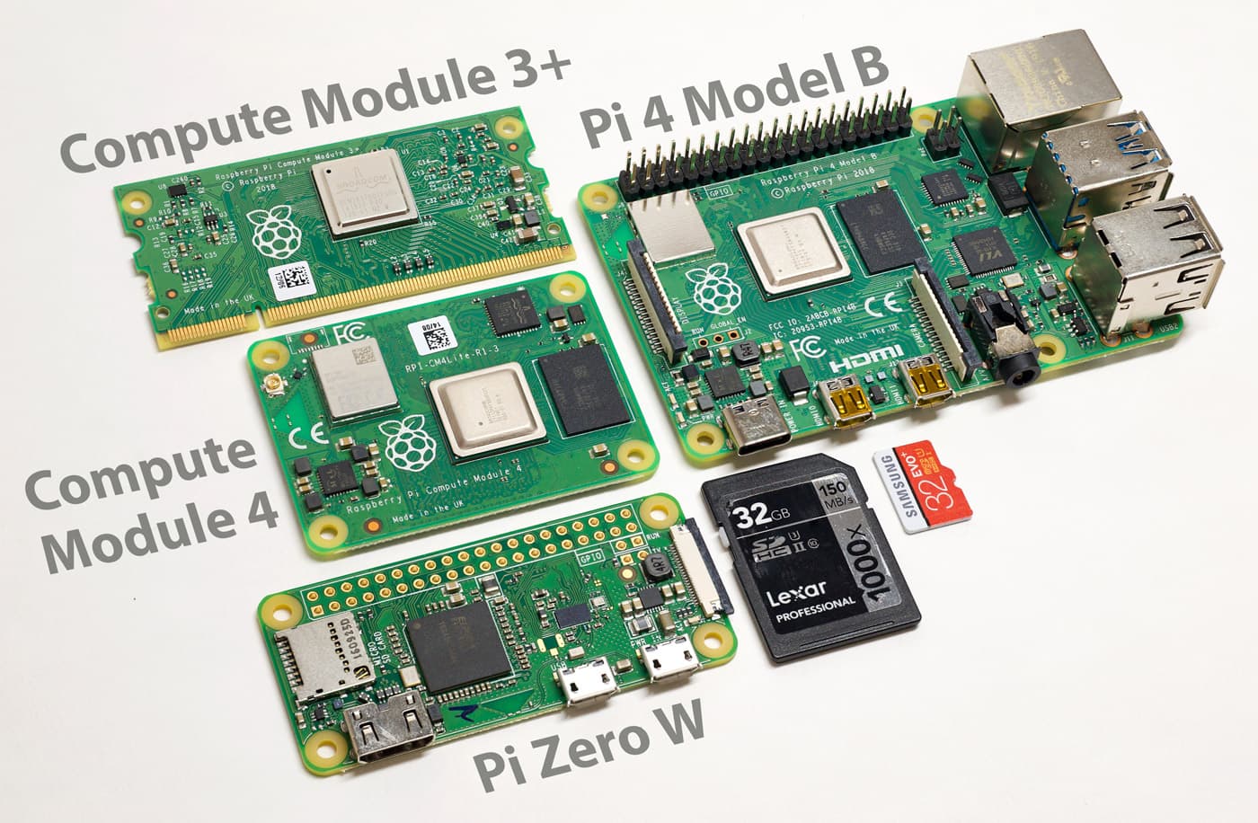
The best picture I could find was an old photo (source - it’s from Jeff Geerling’s blog):
However, the CM4 and CM5 should be the same footprint (55 x 40mm). So it is slightly taller than the Pi Zero W2 (65mm x 30mm).
The main change I guess are the two Hirose 100-pin connectors, for mounting to your PCB.
I basically know next to nothing on PCB design - however, a naive search just now found what seems to be a decent tutorial on designing a carrier board for the CM5. There’s a video version, as well as an accompanying blog post and Github issue.
Not sure if that helps at all?
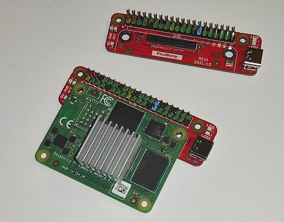
If using a CM4 or CM5, I’d recommend finding a small carrier board that can connect directly to the board, without modifications. Here’s an example of a minimal carrier board that shouldn’t have any issues fitting:
Is the footprint an issue with the Raspberry Pi CM5 vs Pi Zero W2?
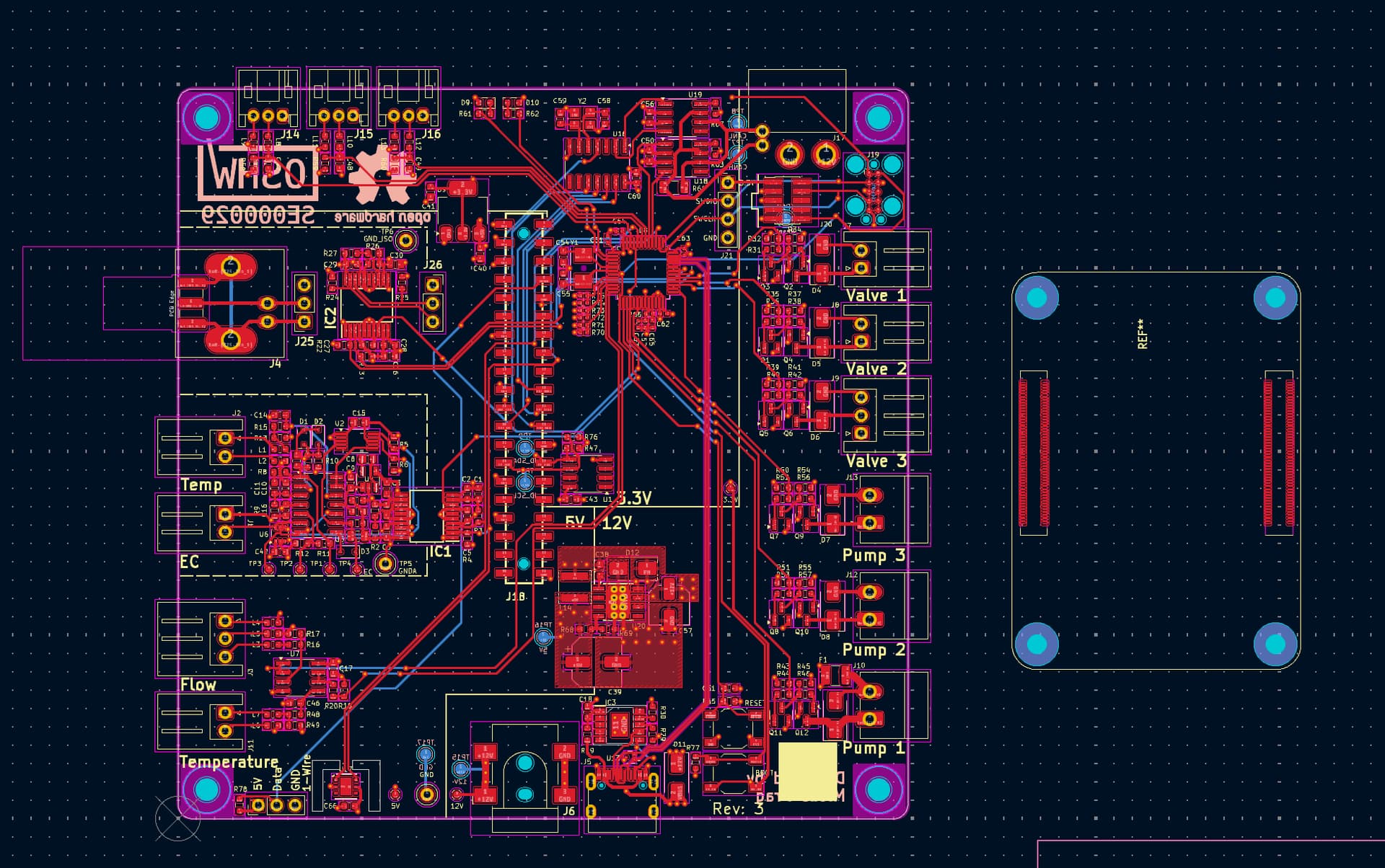
It is not the size of the board but rather the connectors. In the picture below I have placed the CM4/5 module next to RootMaster. Any signals that goes below the connectors on the CM4/5 and the four holes must be moves and rerouted elsewhere. Also, not all components can be placed directly under the CM4/5 either since they may not fit. I am not saying it’s not possible, it is just some work. Therefore I think an easier solution is to have an adapter board. Then we really have a lot of options for a SBC.
@KyleGabriel: The module you link to is really interesting! I will definitely see if I can get my hands on one and experiment some.
I’d definitely be up for buying a couple of the boards - maybe 3-4 of your boards if I can stretch?
Cool ![]() !
!
Hmm - so you’re thinking using an adapter board, that breaks out the CM5’s two 100-pin connectors (or one of them, at least) into a 40-pin GPIO connector, which we then connect to the Rootmaster? (e.g. via a short 40-pin cable).
I couldn’t find the PicoBerry for sale anywhere - it does look pretty cool though.
If you just want to buy something off the shelf, would something like the Waveshare Nano Base Board (A) or the Nano Base Board (B) be another option here?
I was just using it as an example. Really, any carrier board with a 40 pin header will work, it will just depend on clearances and how tall of a header extender is needed (if needed).
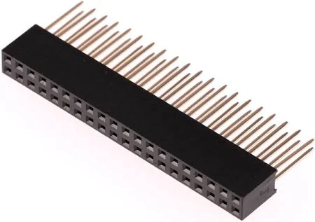
Yes, the Waveshare Nano A or B should work. But both is going to need some extensions to lift it higher or else the connectors will collide with the board. You can probably use something like this to extend it:
I think that would be neat - I’d be interested in buying the daughterboards the same time I buy the main boards. Would it be quite difficult, or take a long time though, for you to create such a daughterboard?