Noise In Sensors When Pi4 PSU Providing Power

When my Pi4 is powered by the genuine Pi4 PSU, the electrical interference is outrageous. Initially I thought it was noise from all the other equipment but one by one I eliminated everything possible to the point i was sitting in the dark. I came across others discussing their systems being powered by a battery and that gave me the idea of testing and eliminating the PSU. I hooked up a portable battery, just a normal phone charger type, and to my delight after many hours of research, testing and purchasing, I had finally found the culprit, that damn Pi4 PSU.
I purchased a Pi5 thinking that a new model would be better but to my surprise, not even close.
I have now gone down a rabbit hole of isolators, buck converters, “clean” power, GND star, separating “dirty” & “clean” devices like relays & sensors etc with seperate power sources to busses including a separate Pi power source, twisted shielded high end cable, non-twisted non-shielded (and other possible combinations) and many other scenarios.

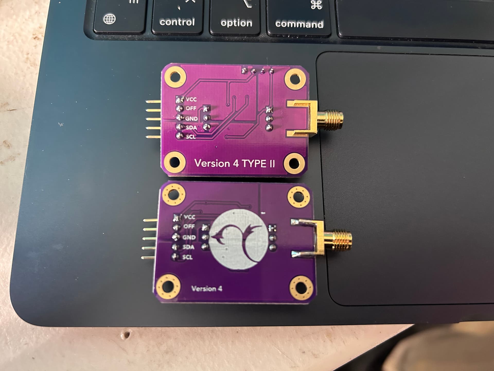
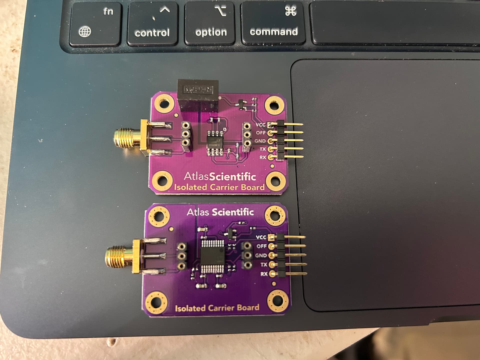
After consulting others that are smarter than me, the general consensus was to use a 24v PSU, LM2596 24-5v Buck, ISO1540, star GND, separate power sources to a clean rail (I2C sensors) and a dirty rail and a XC5015 for the Pi power through the USB-C. The contentious part is how each of those boards are wired in the circuit.

24v PSU, GND star, Buck 24-5v, ISO1540 (Pi’s 3.3v, GND, SDA, SCL on the other side).
One idea presented was to place the buck further downstream where a 5v bus went to the sensor bus and ISO1540 and after a GND bus near the sensors (that was fed to the star), a GND wire went into the buck’s -IN then the -OUT went straight back to that GND bus then to the star. How this would work didn’t make sense to me but while most others disagreed, they understood the concept. Other scenarios were tested (wire gauge, boards positioning, swapping XC and buck, ferrite beads etc).

How would you wire these boards in?
Would you prefer a totally different way/boards?

I do have Qwiicbus End points to try and Pi Pico but surely the original Pi4/5 PSU can’t be that bad and there’s a more obvious answer.

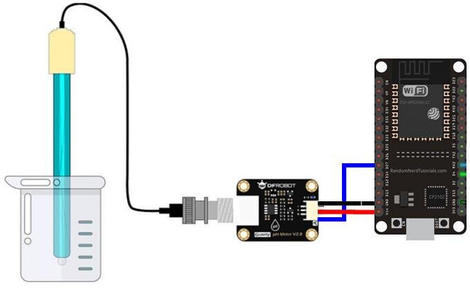
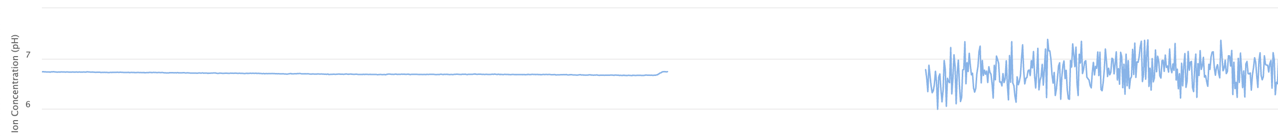
pH sensor is the most affected so it’s the only one i’m referencing going forward.

Screenshot shows the difference between operating on the battery then after it went flat i swapped to the original PSU.

Details:
Pi4
i2c
Atlas sensors
240v mains

Could be the sensor.

I’ve used an Atlas pH sensor without issue in a couple different reservoirs, with only the power isolation board they sell and a regular PS.

Here’s an interesting fact.

I bought 3 new Atlas Elec Iso Carrier boards and when they arrived I noticed 1 was different. 2 of the 3 (and all the others I have purchased) are Version 4 Type 2. The odd one out is Version 4 (I assume Type 1?) and the difference is mA.

Type 1:
5V - 15mA
3.3V - 20mA

Type 2:
5V - 28mA
3.3V - 22mA

Visually, the major difference is the Iso DC/DC Converter is missing on the Type 1 and it also has a larger chip.


I conducted many tests using the old and new pH sensors with each type of board and with the old and new EZO chips on both the Pi4 and Pi5 and the results are telling.

The lower mA board ran with minimal variance between readings using Python script. The high mA board showed the noise quite obviously. Also the Pi4 was the most noisy out of the 2 controllers but still proved to be very efficient with the lower mA board.
As to why an earlier released board would prove to be superior (in my case) is beyond me. Also what seems a little odd to me is the newer board’s 5V is higher than the 3.3V and the opposite applies with the older board. Is this obvious or normal to anyone with knowledge in this area?

I’m not too sure how many of the Type 1 boards are still available but I will have to use the older versions with the pH sensor and the Type 2 boards with other, less sensitive devices.

I will continue to investigate but all this interests me as this is far from my field of expertise. Kyle, I came across your builds after Covid and thought to put myself through a challenge and i’m loving it, but, now unfortunately I have put myself down a deep rabbit hole and expanded quite considerably. Nonetheless it has kept my mind active and enjoying every bit of it, so thanks!

Analog sensors can be inherently noisy. Have you tried installing a 0.1 µF ceramic capacitor across the data input pin and a ground pin on the ADC board to help absorb some of the noise? I would imagine it should already have some filter caps built in, but they may not be enough? ALso, if the sensor driver has any adjustment for oversampling you should set that to 8x or 16x to help further reduce noise or “jitter” in the readings.

An easier option might be to isolate the sensor from the Pi completely by attaching the sensor to an ESP32 running Tasmota and sending the sensor data to Mycodo via wifi using MQTT. I have several ESP32s setup as wifi sensors and they work very reliably.