All,
I have built the Mushroom Cultivation Chamber project. All works beautifully except the PWM fan control. I am using the OSHPark board. Have built two of them but get same result. Even without PWM from Rpi plugged in, the fan runs at 50%. With PWM connected to Rpi, I can control speed up to 100%, but minimum it will go is 50% even when set to 0. With Rpi disconnected, PWM signal is 5v to fan.
I am relatively new at electronics, so probably something simple. Any advice would be appreciated.
I did build the same circuit on a breadboard and it works as expected. Cant figure out what in the circuit would cause it to get 5v PWM with no input.
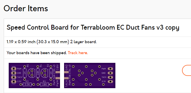
Thank you for your prompt repies. The board I am using, I believe is the board you designed for the project. Not sure if you can see the pic below, but it is the Speed Control Board for Terrabloom EC Duct Fans v3 copy
Regarding voltage, I am probably not explaining correctly. The voltage coming from the terrabloom fan is 10v. I plug the supplied fan cord into the audio jack that is soldered on the board (board not connected to RPi). Output to PWM speed control is 5v.
When I connect the board to the RPi with duty cycle set to 0, then plug the fan into the audio jack. Fan immediately starts at 50%. Speed of the fan does not change until I set the duty cycle greater than 50%.
As mentioned, when I build it on the breadboard all works correctly. I wonder if somehow there is a short on the board that is causing this issue (that is why I built a second one, but same result). But I unfortunately don’t know enough about transistors to figure out where the short or other issue might be that would cause it to get 5 volt output.
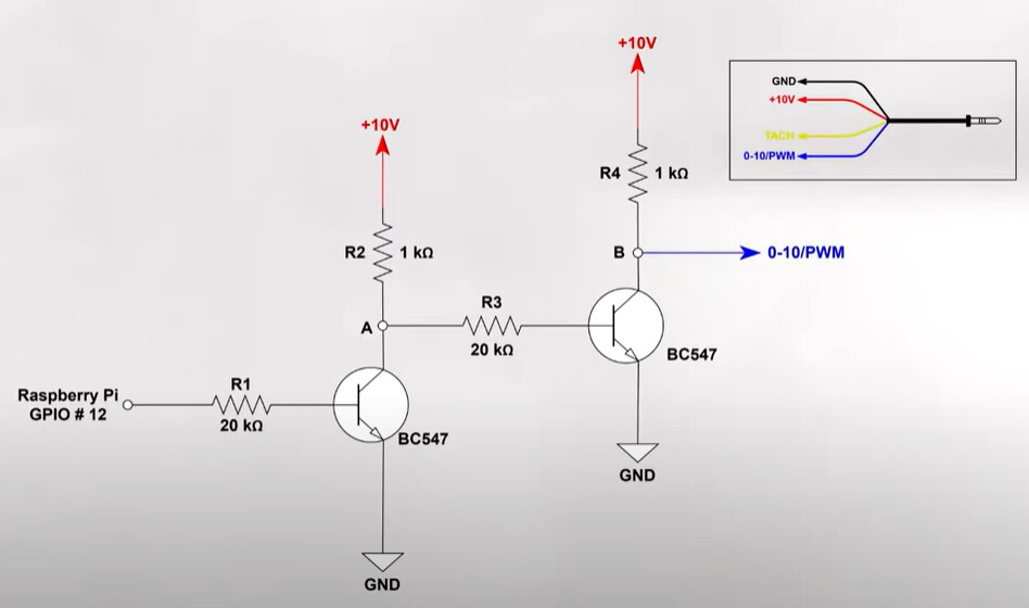
I thought it should be 0-10. 0 for 0 duty cycle and 10 for 100% duty cycle Please refer to the pic below (From Terra Bloom Site). It is basically the same schematic as the OSH Park board except resistance levels are different. I get the 10 volts as shown on the upper endpoints. On the blue 0-10 PWM is where I measure 5V This is without connection to RPi. When connected to RPi, 0 duty cycle set in MyCodo, 0-10/PWM is 5V.
Can you please link to what you’re referring to rather than using photos? Photos don’t allow additional investigation because I have no idea where they came from or who generated them.
This is not how PWM works. PWM does not produce a range of voltages, it operates on one voltage.
The fan can accept either a voltage range between 0 and 10 volts or a PWM signal (at 10 volts).
The only way you can really measure what’s happening is if you have a multimeter that’s capable of measuring frequency or an oscilloscope.
I’m not sure why you’re seeing 5 volts output, but you also haven’t mentioned how you’re measuring the output or provided details of your actual wiring. There are a number of possible issues, such as your measuring instrument, improper transistors, improper soldering/wiring, fan not producing proper 10 volts, etc.
On a side note, because the fan’s speed control circuitry operates with a signal of 0 - 10 volts or PWM at 10 volts, it makes sense you would see 50% speed if you’re providing 5 volts.
Thanks so much for the followup. My multimeter does have frequency and duty cycle, but I had never used it. After your last message, I pulled the old user manual out to learn how to use it!
Result, after doing some checks, figured out the transistors I used are pinned opposite the ones you had specified in the OSH Park description. Problem solved!!! As I said, I am new at this. Learn something new everyday. Now on to the Mushroom growing…I hope!
Hi guys, I am also planning to rebuild the “Speed Control Board for Terrabloom EC Duct Fans v3”, but I have almost no idea about electronics, so I wanted to ask if 1/4 watt resistors are ok (I have some left) or if it should be 1/2 watt or others.
BTW:
Thanks Kyle for this great project, I can’t imagine how much work you must have put in to make something like this. Thanks for that.