Hi
I do not really get how to connect the eg. carrier board to the raspberry.
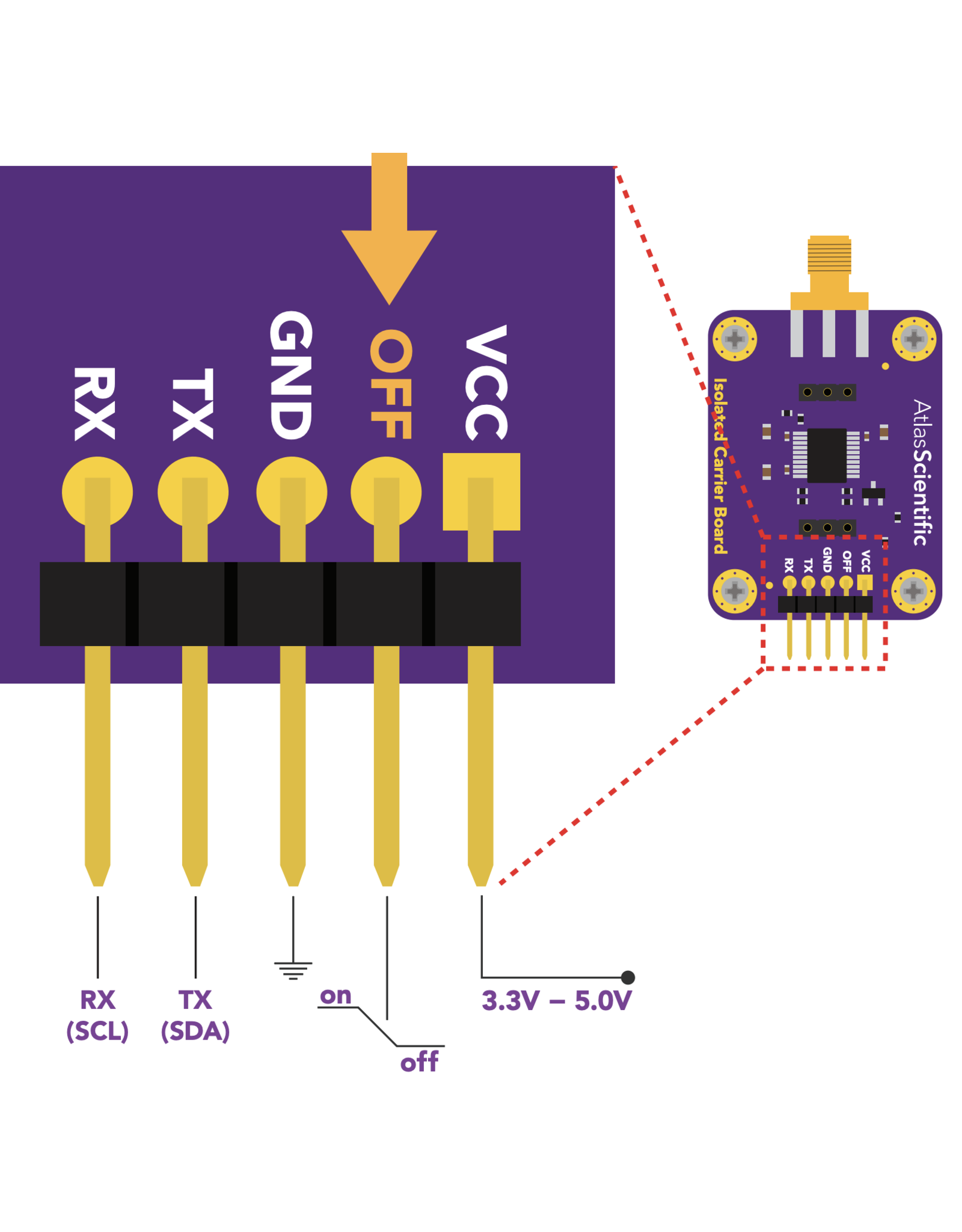
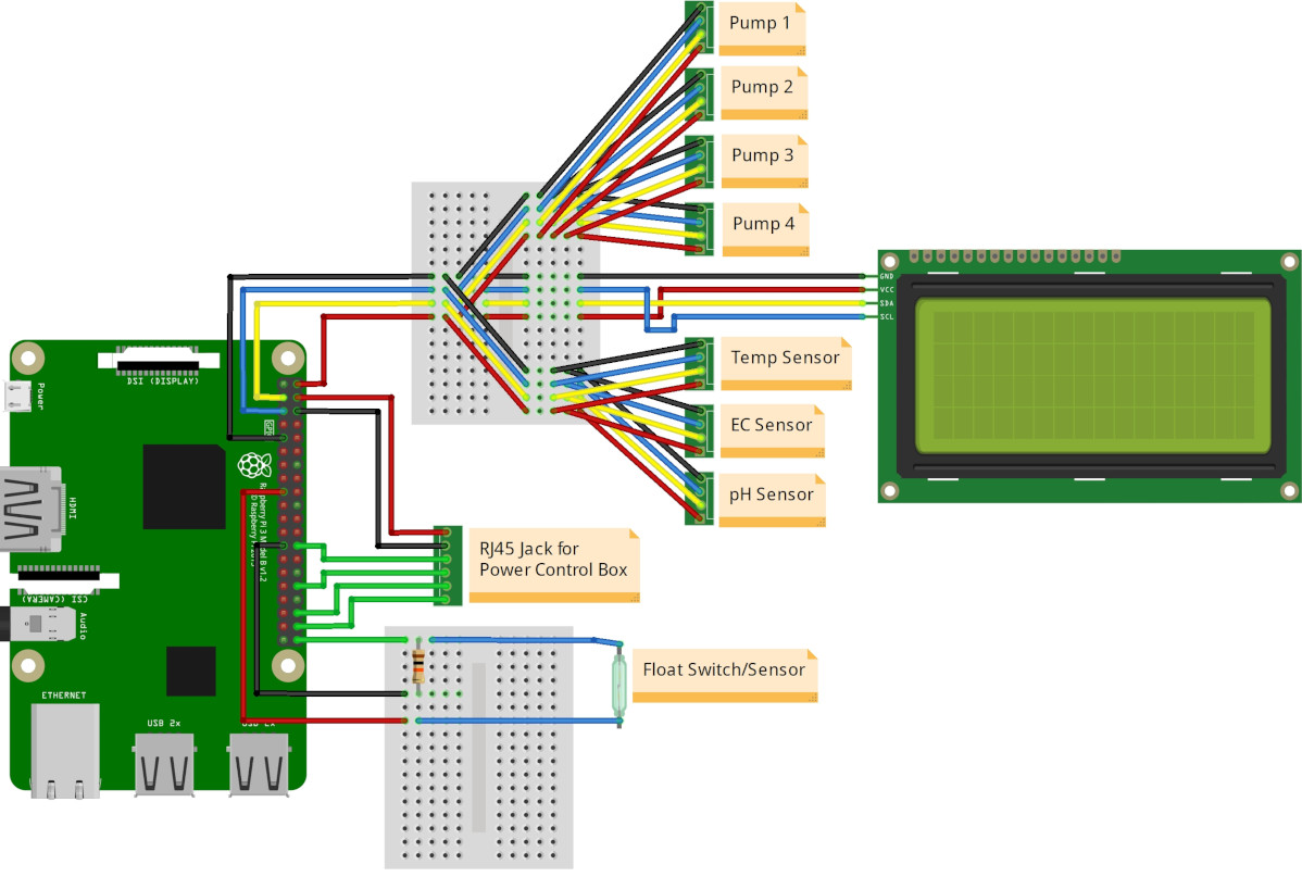
I’ve wired up from GROUND, 5V, GPIO2 and GPIO3. On carrier board we have VCC, OFF, GND, TX and RX. Which do I connect together?
I’ve tried to find out a schema
Hi Jacob
Could you describe what you are trying to connect. Is it an atlas carrier board? If so, there is a lot of documentation on their website.
I2C is not a cross wire thing, so SDA goes to SDA and SCL to SCL. On atlas TX=SDA and RX=SCL
Hi
Thanks!
I was refering to schema
It’s not specified what the pins on raspberry should be connected on into the carrier board. Yes i’m using Atlas.
It seems to be in their documentation ![]() )
)
Fair enough:) Atlas has quite extensive documentation, actually most hardware vendors does. For instance if you look at the carrier board, it has the pinout listed
Luckily for us I2C is really easy to work with, as its just daisy chained.
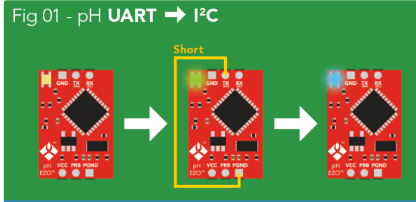
Remember to change the Ezo to I2C if you havent yet. They come standard as UART. A nice guide is also available at the Atlas website
1 Like
I’ve tried to change to I2C, what I understand power on GND, VCC and then connect PGND and TX, the led blinks (white green I guess) all the time and nothing happens?
think I found the solution, connect GRD/VCC after TX/PGND and then release TX