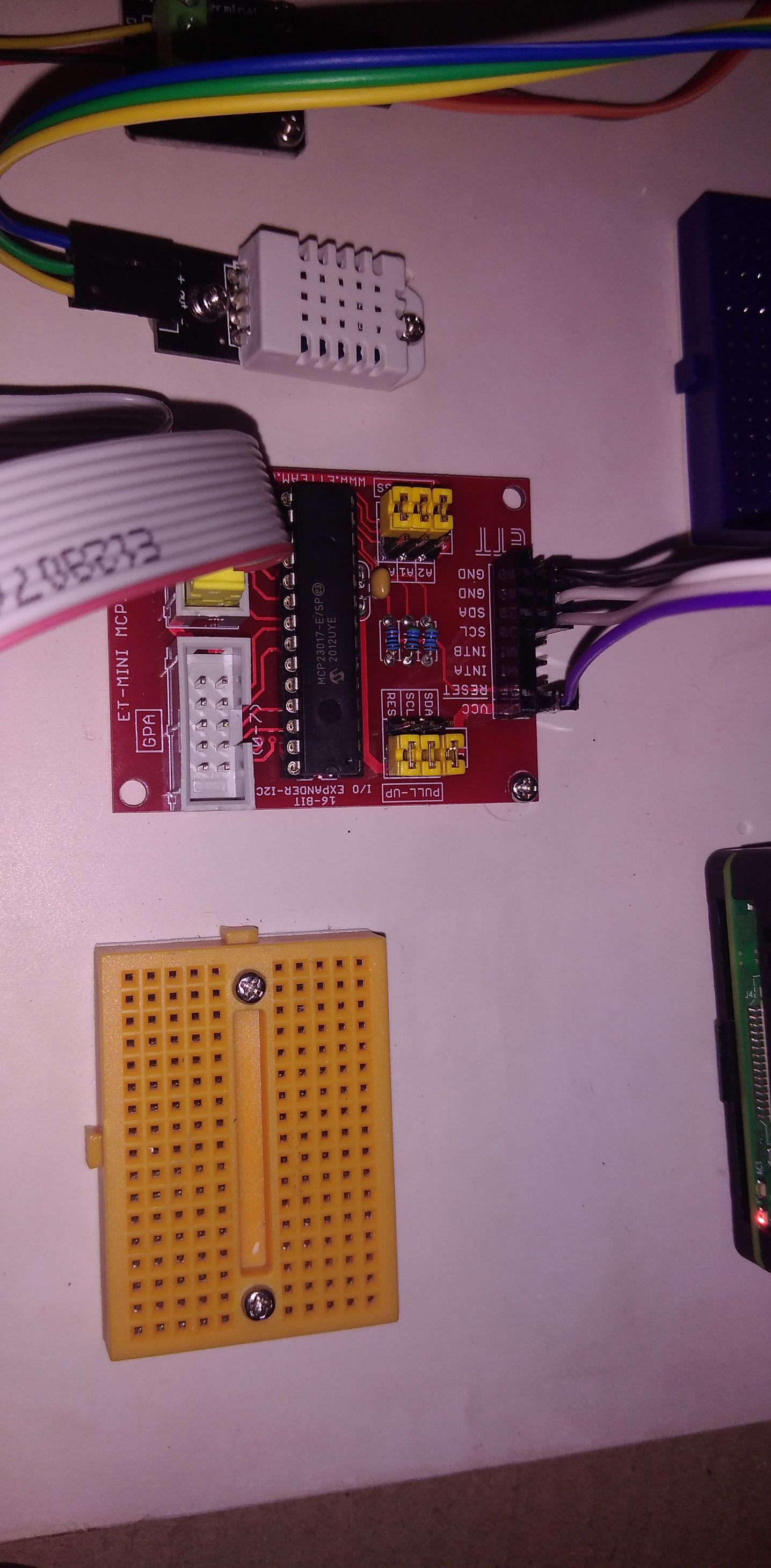
I got a MCP23017 expander board and I can’t get it work.
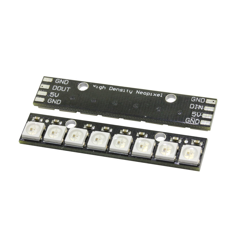
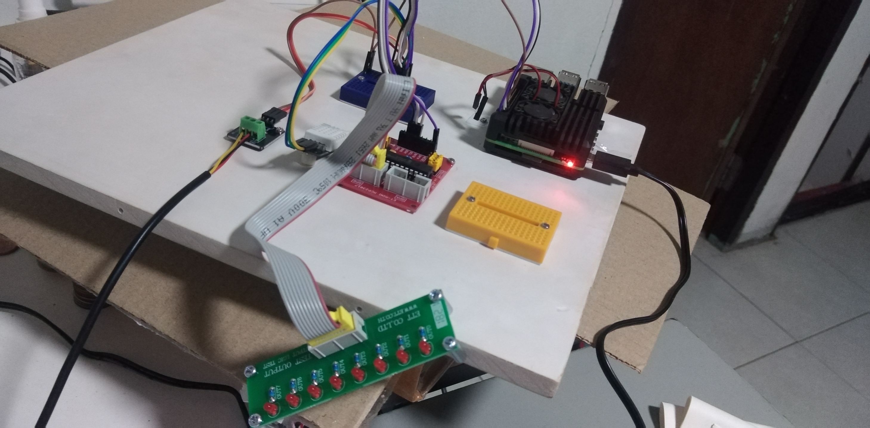
For testing I have connected a 8 LED board.
I have activated the MCP23017 output module in mycodo and I was hoping I can switch the LED’s on and using the “on” and "off’ buttons but nothing happens on the LED side. In mycodo the little success message does pop when pressing those buttons.
The required dependencies are installed.
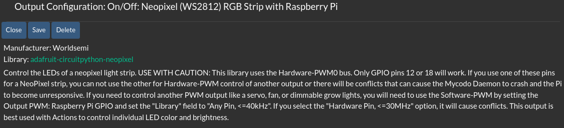
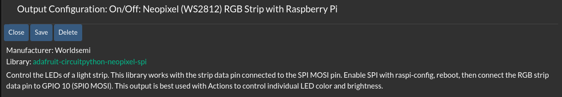
If so, that kind of LED board is only supported in Mycodo when directly connected to the Raspbery Pi’s GPIO-12 or GPIO-18 pins when using the NeoPixel GPIO Output module…
Where are those LED’s sourcing their power from? The Pi’s GPIO?
That’s the main issue I can see from the pics.
Also, Do you have a ground wire going from the GND pin on the expander board all the way back to a ground pin on the Pi?
You should make sure that the expander board and whatever devices are running from it are getting their power from a separate dedicated power source OTHER than the Raspberry Pi’s GPIO pins. If those LEDs are drawing too much current, you’ll damage the Pi.
Other than that, I can’t tell what’s what from the pics, I would need a wiring schematic to understand what you are trying to accomplish.
Just out of curiosity, why do you need an expander, does the Pi not already have enough GPIO pins for what you are trying to do?
Hi Lucid, thanks for your input. I was thinking since flat cable and connects are 10 pins I maybe wrongly assumed that ground was using one of them. I need to check that out.
I have read that an external power source is required when using a lot of current. I think I should apply it to the expander board.
The Pi might have enough I/O to begin with but I want to room to play with so I can add more later. I intend to use this setup to control two rooms next to each other.
Yeah, double check all your wiring, especially grounds, and use a separate power supply on the expander board.
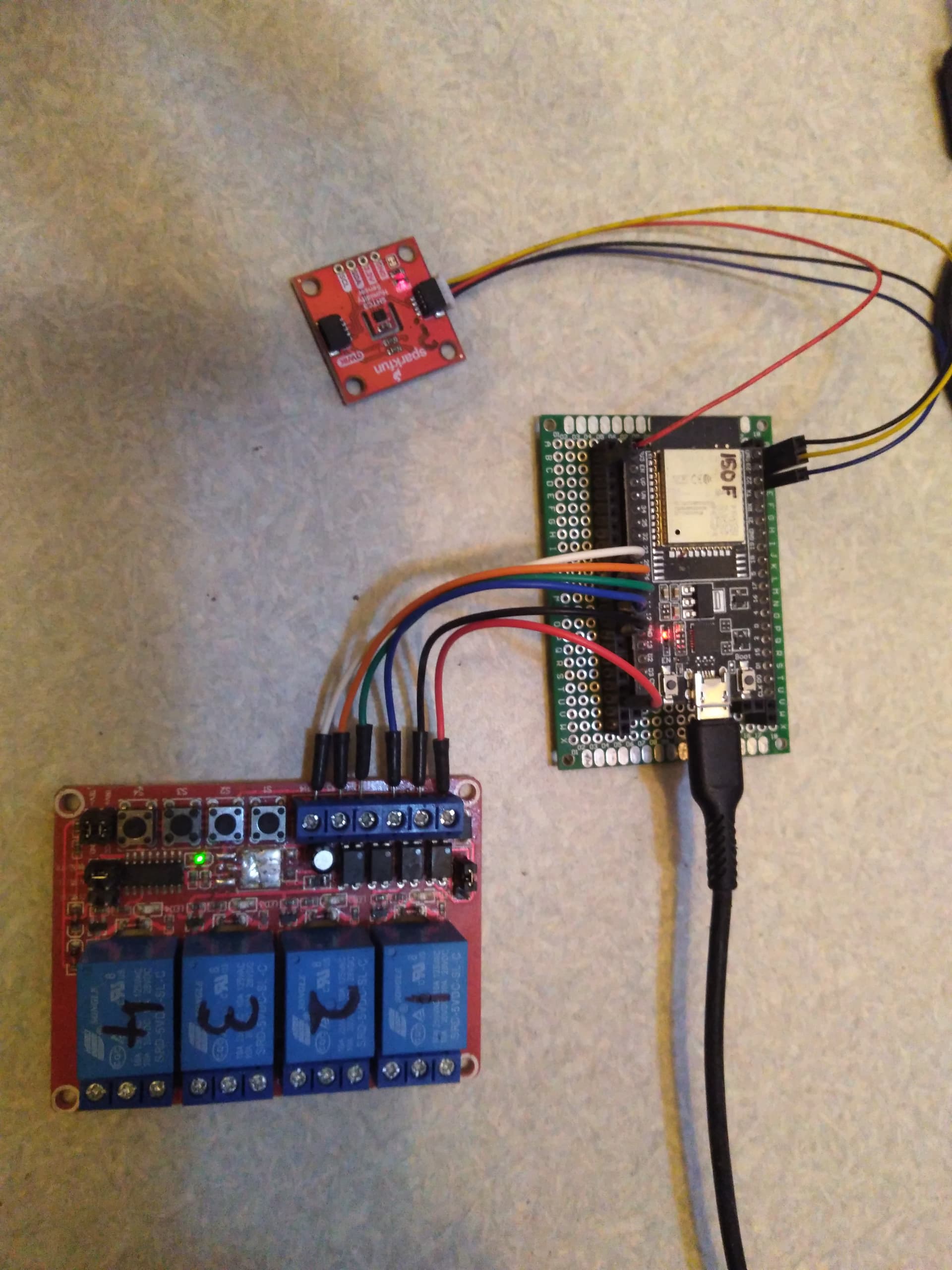
If you are looking for easy I/O expansion, I would also recommend using an inexpensive ESP32 dev board running Tasmota and then you basically have a WiFi GPIO expansion module with 30 more GPIO pins, no need to worry about I2C wire length issues running wires all the way from the pi to the expansion board, and no need to drill holes through your walls for wiring.
You just need to install Mosquitto MQTT broker on the same pi that is running Mycodo, and then you can control the WiFi ESP32 “expander board” using the MQTT modules in Mycodo.
I’ve got an ESP32 now, installed MQTT broker on the Pi and flashed the ESP with the latest Tasmota using the online tool.
I have it connected to the wifi and can log in to the ESP via the webinterface.
What are the next steps make this work?
Is there any recommended article? I found a lot of info but not really related to the use with mycodo.
Another question: How would I configure the MCP23017’s I/O’s as an input?
When setting up an input in Mycodo there is only the option to select the Pi’s GPIO’s.
I’ve never used that board but I’ve do use MQTT so I can give some general information, which I assume is what you’re seeking. It looks like that board is a i2c expander so you can monitor/control devices which are using the same i2c addresses. You say you have the MPC23017 now connected through Tasmota. The Tasmota interface to the ESP32 should give you either sensor readings or switches to control the outputs (I assume). Either way, if you have it connected correctly to your MQTT broker on your Pi, you can use the MQTT topics Tazmota produces to get Mycodo to read or control your devices.
I use MQTT Explorer (highly recommended) on my Mac to examine the topics coming into my broker. It makes it easy to see what is happening and copy the correct topic information. Tasmota, by default, starts it’s topics with “tele” so open that and you will see your ESP device (likely “tazmota-xxxxxx”). Open that for more info like STATUS or STATE which will show sensor readings and the like. If you have it set up for relays, find the device in the “stat” or “cmnd” topics and open it to see the power change states as you toggle the switch on the Tazmota page. Ignore the “tasmota/discovery” topic stuff unless you’re using Home Assistant. Once you find the topic you want to read or control you can use the copy icon to copy and paste easily. you may have to play a bit to figure out what does what. MQTT is powerful and fun once you understand the basics and expands what is possible when you can’t just plug it in the Pi.
Mycodo has the ability to use MQTT for either inputs (subscribe) or outputs (publish) and the topics can be pasted into the appropriate box in those. There are, of course, nuances I didn’t cover but thats the basics.
Hi Billjuv, thanks for the reply.
I was not going to connect the MPC23017 to the ESP since it already has so many input/output pins so I thought there is no advantage in doing so. The MPC23017 stays connected to the pi directly so can have more GPIO there and was wondering how I can use it as input also since there is no input option for MPC23017 in mycodo inputs.
You info is still useful to get me going with the ESP32, thank you!!
I misunderstood. I reread Lucid3y3’s reply to you and paid attention this time… exactly how I deal with it. If you figure out how to make the MCP23017 work let us know
The MPC23017 can only be used for Outputs in Mycodo. If you want to use it as an input you will need to write a custom Input module for it.
To read inputs from the ESP32 over MQTT you will need to setup the MQTT Subscribe Input module in Mycodo. And if you are controlling outputs or relays on the ESP32 through Tasmota, you will need to install the MQTT Publish module in Mycodo.
You should read the MQTT documentation for Tasmota…
You should also download and install a MQTT client app like https://mqtt-explorer.com/ so you can have a nice GUI-based way to see what is happening on your broker and see all the topics being published and how the message data is formatted as you will need this information to enter into the Mycodo MQTT settings.