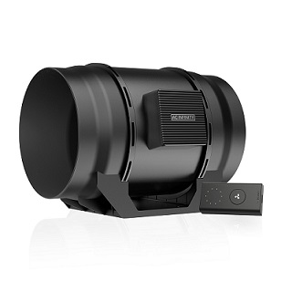
I am attempting to set up a grow tent that has an always-on input fan providing frequent air exchange.
I have set up the code on the Mycodo Software so that when C02 or Humidity is too high or low, the duty cycle will change and the speed of the fan will alter according to the levels of the C02 and humidity.
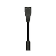
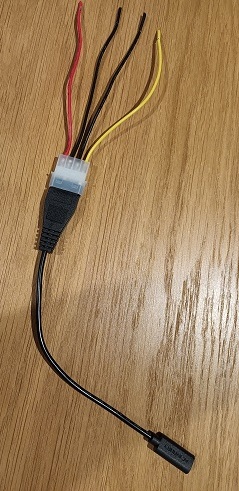
[4-wire Molex female connector attached to the UIS to Molex adapter]
I believe it is possible to connect the four wires from the Molex adapter to the Raspberry Pi 4 B GPIO pins so that the Mycodo code will adjust the PWR duty cycle as per the code.
However, as I am a novice at electronics, I am hesitant to attempt to connect this fan to the Raspberry Pi without some guidance.
I am hoping that someone can tell me which GPIO pins to connect to.
The AC Infinity manual only states that the speed controller is PWM and does not state the voltage.
I emailed AC Infinity support. They read my email but did not respond.
Several Google searches of other people manipulating the speed controller state that the voltage is 10V, but there is no reference to this measurement.
The controller utilizes 3 wires: +10v (red), ground (black), and a yellow wire that is labeled as “PWM”. The 4th wire on the molex is not used and not connected.
Furthermore, there is this link, in which a user is connecting an AC Infinity fan to an RPi, but I am uncertain about their chosen method of connection.
Any suggestions as to how I can connect the fan to my Raspberry Pi would be appreciated.
First of all, if you don’t already have one, buy yourself a good digital VOM meter.
The Raspberry Pi GPIO is only 3.3v signal logic level (signal voltage).
If you input more than 3.3v signal into the GPIO pins, you’ll damage the Pi.
If you try to draw more than 3.3v at 16mA from any single GPIO pin, you’ll damage the Pi.
The total maximum current draw for the entire GPIO bus is 51mA.
The power pins on the Pi (3.3v and 5v) can only supply a maximum of 1.5A.
This means you should not power anything from the Pi’s GPIO except for a few sensors.
Any devices that need more power should have their own separate dedicated power supply (PSU)
To wire your fan:
The red wire goes to your 10v DC power supply to run the fan.
The yellow wire goes to whichever GPIO pin on the Pi you have configured for the PWM output.
In most DC circuits, ground is common, so your black ground wire must go to the DC power supply to complete the circuit for the fan, and also split off and go to a GPIO ground pin on the Pi to complete the circuit for the PWM signal.
Most quality fans have internal resistors that prevent the PWM input from drawing too much current from the PWM source.
If the fan’s PWM input requires a different signal voltage other than the 3.3v that the Pi GPIO outputs, you will need to use a logic-level shifter circuit that brings the PWM signal voltage to the same logic-level that the fan uses for it’s PWM input. Most fans need somewhere between 3.3v and 5v for the PWM input signal. Try the 3.3v first, it will most likely work.
It is indeed a 10 VDC PWM signal the fan needs. As mentioned, the GPIOs of a Pi should not be connected to anything other than 3.3 VDC. I’m surprised their documentation leaves out this critical piece of information. If you look at the Terrabloom speed controlled fan manual, it is well-documented how to control the fan speed. Anyway, rather than just give you the answer, I was hoping it would be a simple exercise in finding the right information in the manual (who knew it would be virtually non-existent and you would be scouring forums). Anyway, I addressed this in some of my build articles/videos. You can find a circuit and board I put together in the BOM at Mushroom Cultivation Automation: From Foraging to Fruiting – Projects | Kyle Gabriel titled Fan Speed Control Board, which will take you to the OshPark website at OSH Park ~ if you wanted to have them print you some boards. There is additional information there for how to assemble and use them as well as alternate versions.
Wow… it’s actually 10v PWM logic level? That seems crazy.
This is why I prefer using $15 computer fans as opposed to paying $150 for a “specialized hydroponics fan”
This way you can keep your 3v and 10v circuits separated.
They don’t handle a lot of amperage, but for signals, maybe they’ll work. They’re also pretty fun! I’ve used these in the past to bypass a button so that I could toggle it via Arduino and to read the state of an LED by removing the LOD and putting the opto coupler in between it
The benefit of using the board I made is it also has the ability to measure the fan blade RPM using the yellow tachometer wire. I know the Terrabloom fans have this, and I’m fairly sure that’s also what the yellow wire is on the AC Infinity fans. This allows you to verify the fan is indeed operating when you instruct it to turn on.
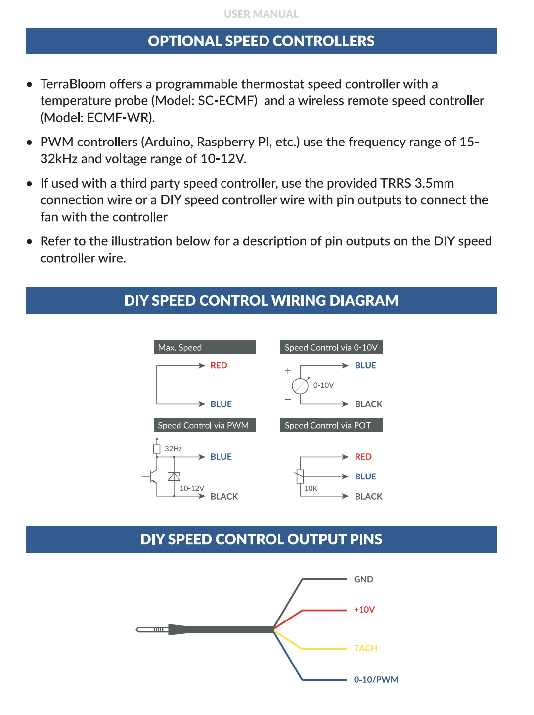
Here’s the great documentation in the Terrabloom manual:
Thanks for your reply. The information is helpful.
One last question about the PCB you recommend. If I purchase two 4" terrabloom fans (one for input and the second for extraction), will I require two of your PCB’s - one PCB for each fan?
I’ve been looking into these AC Infinity fans as well as they are recommended by “Oak & Spore”, which the friend I’m building the Mycodo controls for is fond of. They really want to sell you their controllers and everything else is “unsupported”. I finally found the following on a Hubitat forum, but haven’t personally verified.
The AC Infinity wire colours correspond as follows:
Red = +10 Volts to power controller (does not vary with motor speed changes)
Black = ground for +10 Volt power from controller or 0-10 Volt control (does not change with motor speed changes)
Yellow = + 0-10 V signal to control motor speed.
White = Tach Signal.
I just ordered Kyles’s Terrabloom boards from OSH Park. Though designed to use Terrabloom’s audio connector they should work with any EC fan (the other 2 “alternate versions” now come up as “content missing” though they were there a few weeks ago). 3 was the minimum order.
Curious, following your links I still get a “content missing“ message for both alternative boards from Safari on both my Mac and iPad. No matter to me but…
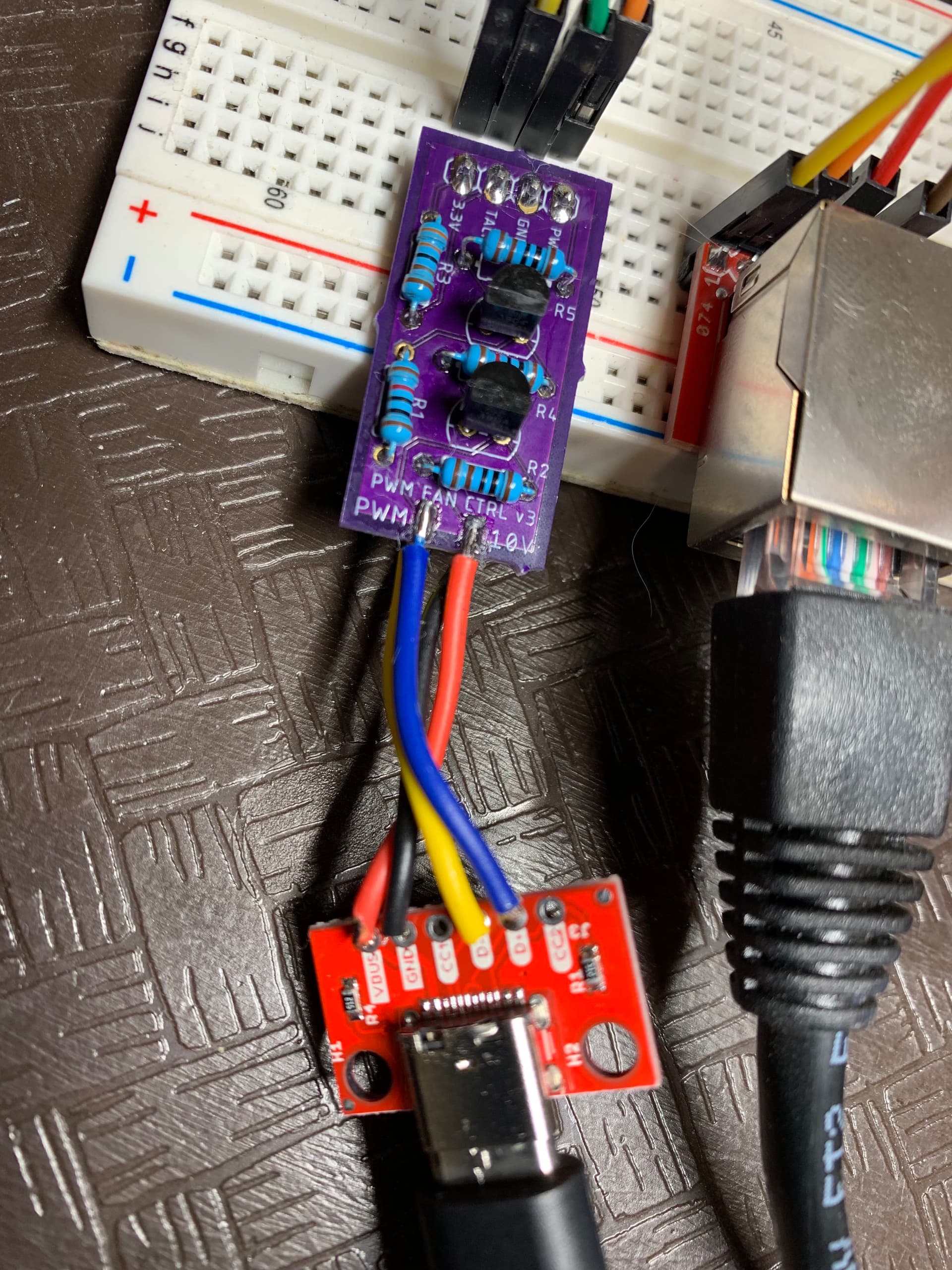
I thought I’d share the following for 6233114 and anyone else who is wondering how to wire up the Type C connectors (on at least VIVOSUN and likely the AC Infinity EC fans) to Kyle’s Terrabloom fan boards instead of the TRRS socket.
I got a VIVOSUN AeroWave E6 EC fan which uses the Type C USB (“SGS”) cable and their “Type C to MOLEX & AUX Adapter Dongle” to sort this out. I’ve attached photos showing wiring from Kyle’s board which is designed for the TRRS plug (not using this connector) wired to a female USB C breakout board I had around.
Kyle’s board to Type C breakout board
GND → GND
10V → VBUS
PWM → D+
TACH → D-
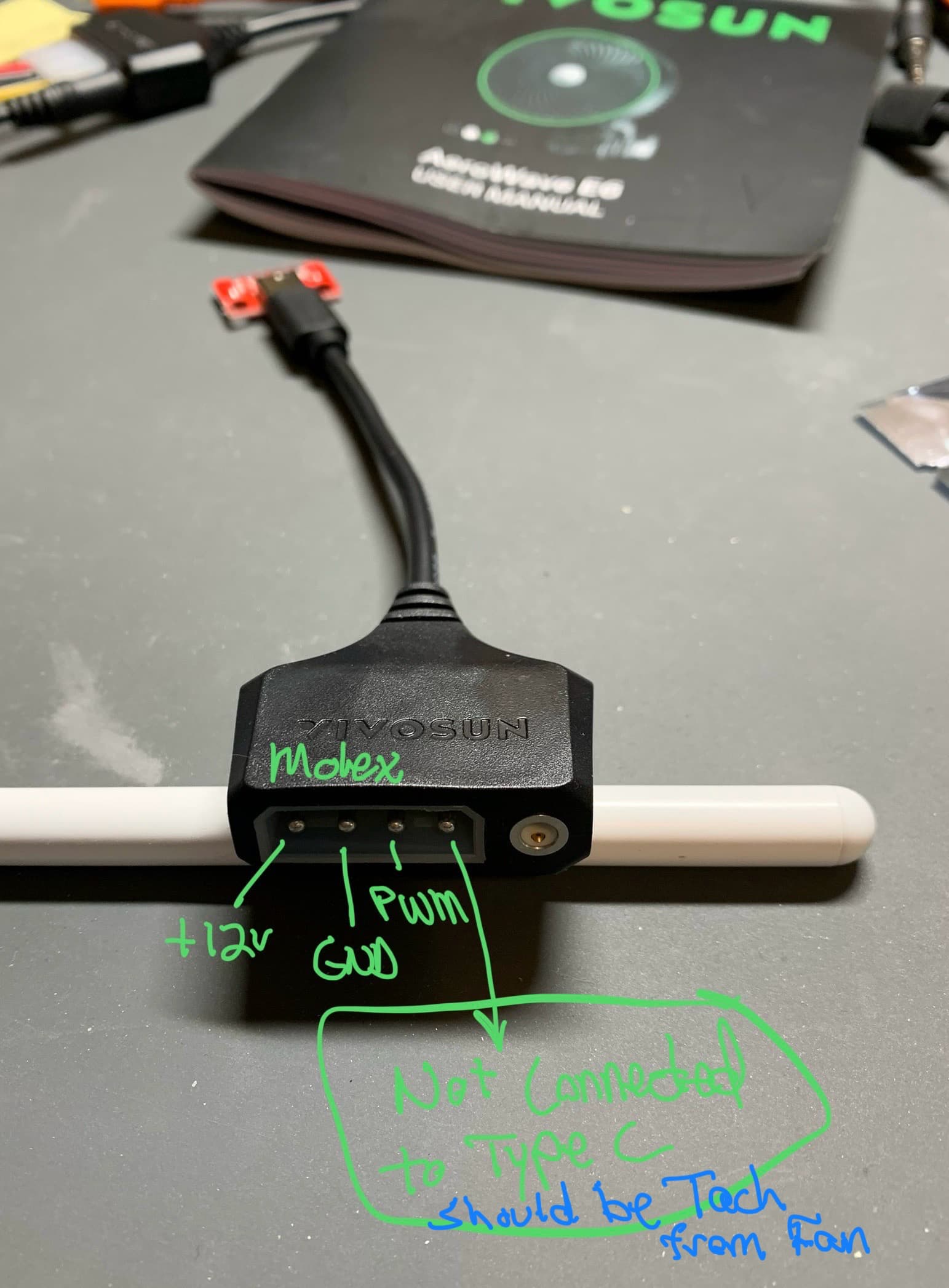
I also show the Molex wiring scheme I figured out as well for the “VIVOSUN SGS Convertor. They state this dongle also works for AC Infinity fans which implies the USB wiring scheme is the same. *This adapter only passes 3 wires through the Type C connector (10v, GND, and PWM) for the Molex and the one I got from Amazon only passes GND and PWM through the 3.5 mm AUX socket so it is useless (assuming a defective dongle). It’s a shame neither of these companies document this and only want to sell you their controllers.
Note: The Vivosun E6 fan is not designed to use the fourth “Tach” wire as Terrabloom fans do, so no feedback signal is sent. I don’t know if their bigger fans, or any of the AC Infinity fans have this feature - if anyone knows which fans do (other brands as well), please let me know as I think this feedback is important and I’ll be needing larger fans soon.
As for actually using the PWM output in Mycodo, I’m still unsure of how to determine the best/proper frequency setting in the PWM Output Configuration but, for my little fan, I’m finding 250 Hertz gives me the widest range of usable Duty Cycle (18-97%).
Regards, Bill
P.S. Matt, I replied a few times to your PM and never heard back. Perhaps emails are in your junk folder…
Came across this thread. I can confirm this does work with AC Infinity blowers. I purchased 5v-24v Optocoupler Isolation Boards on AMZ with NPN output. I’m using this for my 3D printing enclosure driven by an Octopus mainboard running Klipper firmware. The pwm signal is sent from the board to the opto isolator and then to a 4-pin USB-C breakout board. I’m also reading the tach signal back into Klipper. Usable range is 12-100% pwm at 1khz, reading back 500-3000rpm. I had to invert the output signal, but otherwise it was cake. This is using a Cloudline 6" non-Pro version. The 4" Cloudline PRO yields about 300-2700 rpm, same pwm settings.