Hello people!
It’s been a while since I’ve posted on the forums. I’m making this post to share a working circuit schematic i found and modified to convert the raspberry’s 3,3v PWM to an analog 0-10v control signal.
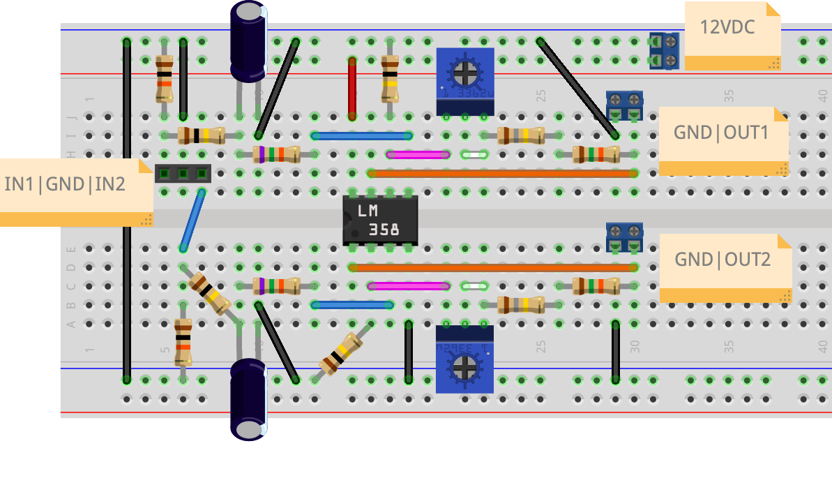
The circuit makes use of the LM358 amplifier’s dual channels to allow simultaenous conversion of two PWM signals. An external 12VDC power source is required to power the amplifier, usually this is supplied by the device that will be controlled.
The potentiometers at R3 act as variable resistors to fine-tune the amplification gain for the respective channel. All-in-all R3 requires a resistance of ~200k Ohm.
The circuit has been tested and is working, maybe someone feels up to the task of designing a clean-looking PCB for it?

Cheers!
lemonsquash