Just been experimenting with my dht22 sensor. I’m using an old ethernet cable that’s about 5m long which is the length I need the sensor to be. when I wired all the wires up like this the readings were wrong. When the signal wire was 5m and vcc and gnd was short I got correct readings. Anyone know how I should wire this thing up so I can have it 5m away from my pi? Or I’m open to buying a different sensor if there’s a better solution.
If you can’t re-design your system to get the Pi closer to where your sensors need to be, then the easiest way around the distance issue is a WiFi sensor. You can attach your sensor to a $5 ESP32 dev-kit board and run the Tasmota firmware on it and have it broadcast the sensor data over WiFi to the Mycodo Pi via the MQTT protocol. You would need to run the Mosquitto broker (server) on the same pi as Mycodo (or it’s own dedicated machine).
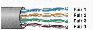
Assuming you are using the I2C interface? Using twisted pair wire for i2c isn’t the best choice since the twisted pair will create more line capacitance, which is exactly what you don’t want on an i2c cable. Also, the 5m length is really pushing the limits of the i2c bus protocols… i2c was originally only meant for inter-chip communications on the same circuit board… only inches apart. You can push lengths up to 5m, but you need to use non-twisted-pair cable, and you’ll need to reduce the baud-rate of the bus. If you only have the twisted-pair CAT-5 cable, then don’t place your data lines on the same pair, and also don’t place your ground or DC positive wires on the same pairs as your data. So as an example… you would either use only the 4 striped wires, or the 4 solid wires for VCC, GND, SDA, SCL. That way none of your i2c bus wires are ever on the same pair. The unused wires should not be connected or grounded. Realistically though, 5m of cable directly connected to the i2c bus is going to give you a lot of line capacitance and a lot of EMI… you’ll be lucky to get any stable readings.
OR…
You can use adapters that change the type of signal to make it capable of much longer transmission distances. These adapters change the signal type into one that does use a standard CAT-5 network cable.
Adafruit has this active terminator…
And Sparkfun has these end-point adapters that allow you to use up to 100 feet of CAT-5. (You need one adapter at each end of your CAT-5 extension cable however long it is. Also, these do not plug into your router, the RJ45 connector is so you can use standard CAT-5 ethernet cables as your extension lines.)
They also have a mid-point adapter so you can drop sensors anywhere along the run.
1 Like
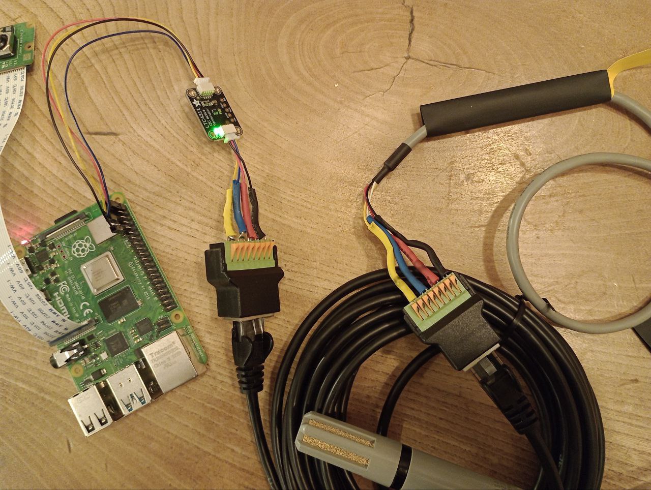
FWIW, I just installed the LTC4311 and wired ethernet jacks on either end so I can run Cat5 cable between my Pi and some of my sensors. Threw all sorts of comm errors until I put in the 4311, now my logs are blissfully quiet.
2 Likes
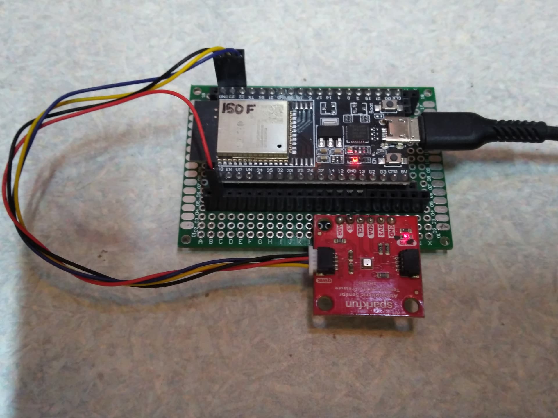
I bought an LTC4311 and an AM2315C. Just plugged everything in but I’m not getting any readings on my dashboard. Can you see anything immediately wrong with how I’ve wired it up?
2023-11-09 21:08:37,064 - ERROR - mycodo.inputs.python_code_24dff363 - InputModule raised an exception when taking a reading: invalid syntax (input_python_code_24dff363-4d2f-4da3-bc3e-f80bac538f98.py, line 58)
2023-11-09 21:08:37,064 - ERROR - mycodo.controllers.controller_input_24dff363 - StopIteration raised 3 times. Possibly could not read input. Ensure it's connected properly and detected.
2023-11-09 21:08:39,555 - ERROR - mycodo.inputs.am2315_b1d99a98 - Initialization errored 3 times; giving up. Maybe the following traceback can help diagnose the issue.
Traceback (most recent call last):
  File "/var/mycodo-root/mycodo/abstract_base_controller.py", line 57, in try_initialize
    self.initialize()
  File "/home/pi/Mycodo/mycodo/inputs/am2315.py", line 105, in initialize
    self.sensor = AM2315(self.input_dev.i2c_bus)
                  ^^^^^^^^^^^^^^^^^^^^^^^^^^^^^^
  File "/home/pi/Mycodo/mycodo/inputs/am2315.py", line 173, in __init__
    self.bus = self.i2c.I2CMaster(int(bus))        # quick2wire master
               ^^^^^^^^^^^^^^^^^^^^^^^^^^^^
  File "/var/mycodo-root/env/lib/python3.11/site-packages/quick2wire/i2c.py", line 48, in __init__
    self.fd = posix.open("/dev/i2c-%i"%n, posix.O_RDWR|extra_open_flags)
              ^^^^^^^^^^^^^^^^^^^^^^^^^^^^^^^^^^^^^^^^^^^^^^^^^^^^^^^^^^
FileNotFoundError: [Errno 2] No such file or directory: '/dev/i2c-1'
2023-11-09 21:08:39,558 - INFO - mycodo.controllers.controller_input_b1d99a98 - Activated in 10254.8 ms
2023-11-09 21:08:39,559 - ERROR - mycodo.inputs.am2315_b1d99a98 - Error 101: Device not set up. See https://kizniche.github.io/Mycodo/Error-Codes#error-101 for more info.
How is anyone supposed to see if you wired anything wrong without knowing the pinout for that sensor?
If you are asking questions about correct wiring, then a wiring diagram done in Fritzing or similar app would be much more useful than a picture of a bunch of wires.
Silly question, but are you sure you have the i2c bus enabled on the Pi and you rebooted the Pi after enabling it?
Have you looked in the Mycodo System Information page to see if your sensor is actually being detected and if it’s address is appearing on the i2c bus?
Are you checking if you’re getting any measurements on the Live Measurements page instead of your dashboard?
Are you sure the STEEMA connectors are fully seated?
It’s almost impossible to see any wiring detail in that picture, but it looks like the plugs might not be fully seated on the LTC4311?
If 5v isn’t working, have you tried 3.3v instead?
Also, are you sure you have the SDA and SCL wired correctly and not reversed?
Did you test the pinout of that CAT-5 cable with a VOM while it’s plugged into your terminal blocks to determine if it’s a standard straight-through cable?
Did you test the sensor hooked up all by itself to the Pi make sure it is still working?
Do you get measurements without it?
No. I just tried without the LTC4311 (sensor plugged directly into the pi) and it still doesn’t work. I should’ve done that before connecting the ethernet. I have switched my sensor over to AHTx0 in the input section after finding this post. I have switched the SDA and SCL wire and tried 5v and 3.3v with no luck
ValueError: No I2C device at address: 0x38
2023-11-10 00:47:18,865 - ERROR - mycodo.inputs.ahtx0_circuitpython_5ef70a89 - Initialization errored 3 times; giving up. Maybe the following traceback can help diagnose the issue.
Traceback (most recent call last):
  File "/var/mycodo-root/env/lib/python3.11/site-packages/adafruit_bus_device/i2c_device.py", line 175, in __probe_for_device
    self.i2c.writeto(self.device_address, b"")
  File "/var/mycodo-root/env/lib/python3.11/site-packages/busio.py", line 207, in writeto
    return self._i2c.writeto(address, buffer, stop=True)
           ^^^^^^^^^^^^^^^^^^^^^^^^^^^^^^^^^^^^^^^^^^^^^
  File "/var/mycodo-root/env/lib/python3.11/site-packages/adafruit_blinka/microcontroller/generic_linux/i2c.py", line 60, in writeto
    self._i2c_bus.write_bytes(address, buffer[start:end])
  File "/var/mycodo-root/env/lib/python3.11/site-packages/Adafruit_PureIO/smbus.py", line 303, in write_bytes
    self._device.write(buf)
OSError: [Errno 121] Remote I/O error

During handling of the above exception, another exception occurred:

Traceback (most recent call last):
  File "/var/mycodo-root/env/lib/python3.11/site-packages/adafruit_bus_device/i2c_device.py", line 181, in __probe_for_device
    self.i2c.readfrom_into(self.device_address, result)
  File "/var/mycodo-root/env/lib/python3.11/site-packages/busio.py", line 197, in readfrom_into
    return self._i2c.readfrom_into(address, buffer, stop=True)
           ^^^^^^^^^^^^^^^^^^^^^^^^^^^^^^^^^^^^^^^^^^^^^^^^^^^
  File "/var/mycodo-root/env/lib/python3.11/site-packages/adafruit_blinka/microcontroller/generic_linux/i2c.py", line 67, in readfrom_into
    readin = self._i2c_bus.read_bytes(address, end - start)
             ^^^^^^^^^^^^^^^^^^^^^^^^^^^^^^^^^^^^^^^^^^^^^^
  File "/var/mycodo-root/env/lib/python3.11/site-packages/Adafruit_PureIO/smbus.py", line 170, in read_bytes
    return self._device.read(number)
           ^^^^^^^^^^^^^^^^^^^^^^^^^
OSError: [Errno 5] Input/output error

During handling of the above exception, another exception occurred:

Traceback (most recent call last):
  File "/var/mycodo-root/mycodo/abstract_base_controller.py", line 57, in try_initialize
    self.initialize()
  File "/home/pi/Mycodo/mycodo/inputs/ahtx0_circuitpython.py", line 62, in initialize
    self.sensor = adafruit_ahtx0.AHTx0(
                  ^^^^^^^^^^^^^^^^^^^^^
  File "/var/mycodo-root/env/lib/python3.11/site-packages/adafruit_ahtx0.py", line 49, in __init__
    self.i2c_device = I2CDevice(i2c_bus, address)
                      ^^^^^^^^^^^^^^^^^^^^^^^^^^^
  File "/var/mycodo-root/env/lib/python3.11/site-packages/adafruit_bus_device/i2c_device.py", line 62, in __init__
    self.__probe_for_device()
  File "/var/mycodo-root/env/lib/python3.11/site-packages/adafruit_bus_device/i2c_device.py", line 184, in __probe_for_device
    raise ValueError("No I2C device at address: 0x%x" % self.device_address)
ValueError: No I2C device at address: 0x38
2023-11-10 00:47:18,871 - INFO - mycodo.controllers.controller_input_5ef70a89 - Activated in 10247.5 ms
2023-11-10 00:47:18,873 - ERROR - mycodo.inputs.ahtx0_circuitpython_5ef70a89 - Error 101: Device not set up. See https://kizniche.github.io/Mycodo/Error-Codes#error-101 for more info.
pi@raspberrypi:~ $ sudo raspi-config nonint get_i2c
0
pi@raspberrypi:~ $ sudo i2cdetect -y 1
     0  1  2  3  4  5  6  7  8  9  a  b  c  d  e  f
00:                         -- -- -- -- -- -- -- --
10: -- -- -- -- -- -- -- -- -- -- -- -- -- -- -- --
20: -- -- -- -- -- -- -- -- -- -- -- -- -- -- -- --
30: -- -- -- -- -- -- -- -- 38 -- -- -- -- -- -- --
40: -- -- -- -- -- -- -- -- -- -- -- -- -- -- -- --
50: -- -- -- -- -- -- -- -- -- -- -- -- -- -- -- --
60: -- -- -- -- -- -- -- -- -- -- -- -- -- -- -- --
70: -- -- -- -- -- -- -- -- ```I had the i2c bus set to the wrong value and it works now with just the sensor. I’m going to carefully solder everything back together tomorrow and hopefully it will work with the ethernet. my bad.
1 Like
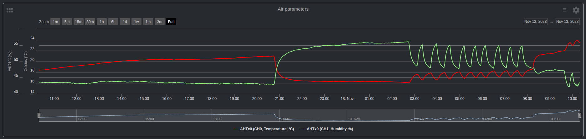
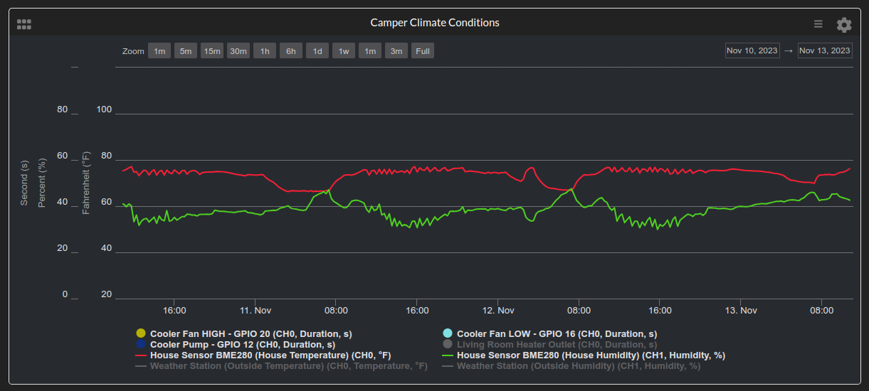
update: It’s working now with the ethernet cable. Actually its been working well for a few days and the line on the chart is smooth and as expected. This morning I woke up and saw these weird spikes. I’m unsure if this is something that actually happened in the room or due to faulty hardware but I think its the latter. pic related.
1 Like
Well, given their even time spacing and what time they happened, I’m going to guess those oscillations are the normal operation of your house heater being turned on and off by your thermostat late at night as your house got cold.
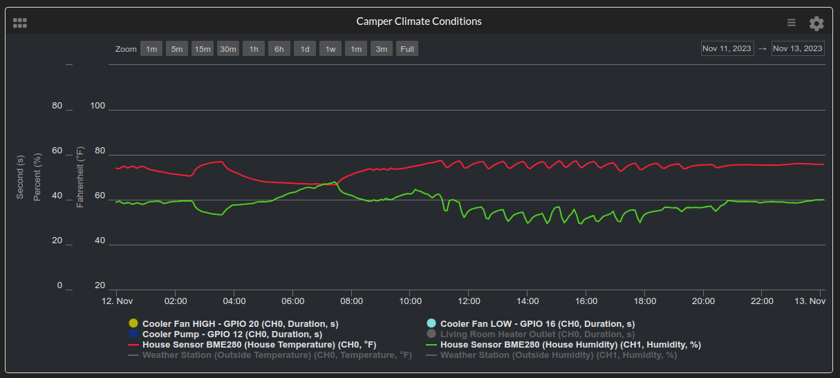
Here’s my graph for my house temp and humidity. The ‘jagged’ parts of the graph show when my house A/C is running… this is what it looks like for an output being run by a bang-bang type of thermostat. Completely normal, your graph lines will almost never be “smooth” if you are running a bang-bang controller (which is what most home thermostats are).
2 Likes