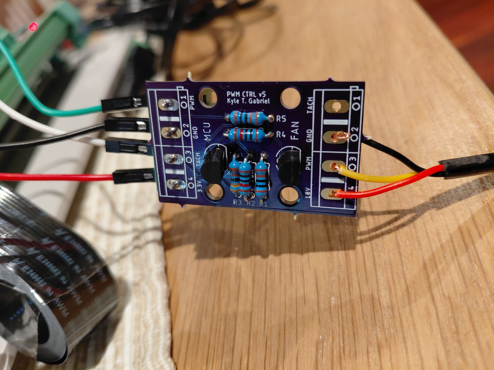
I have correctly soldered and tested the required transistors and resistors to 2 of the speed control boards - I have the same result with both speed control boards.
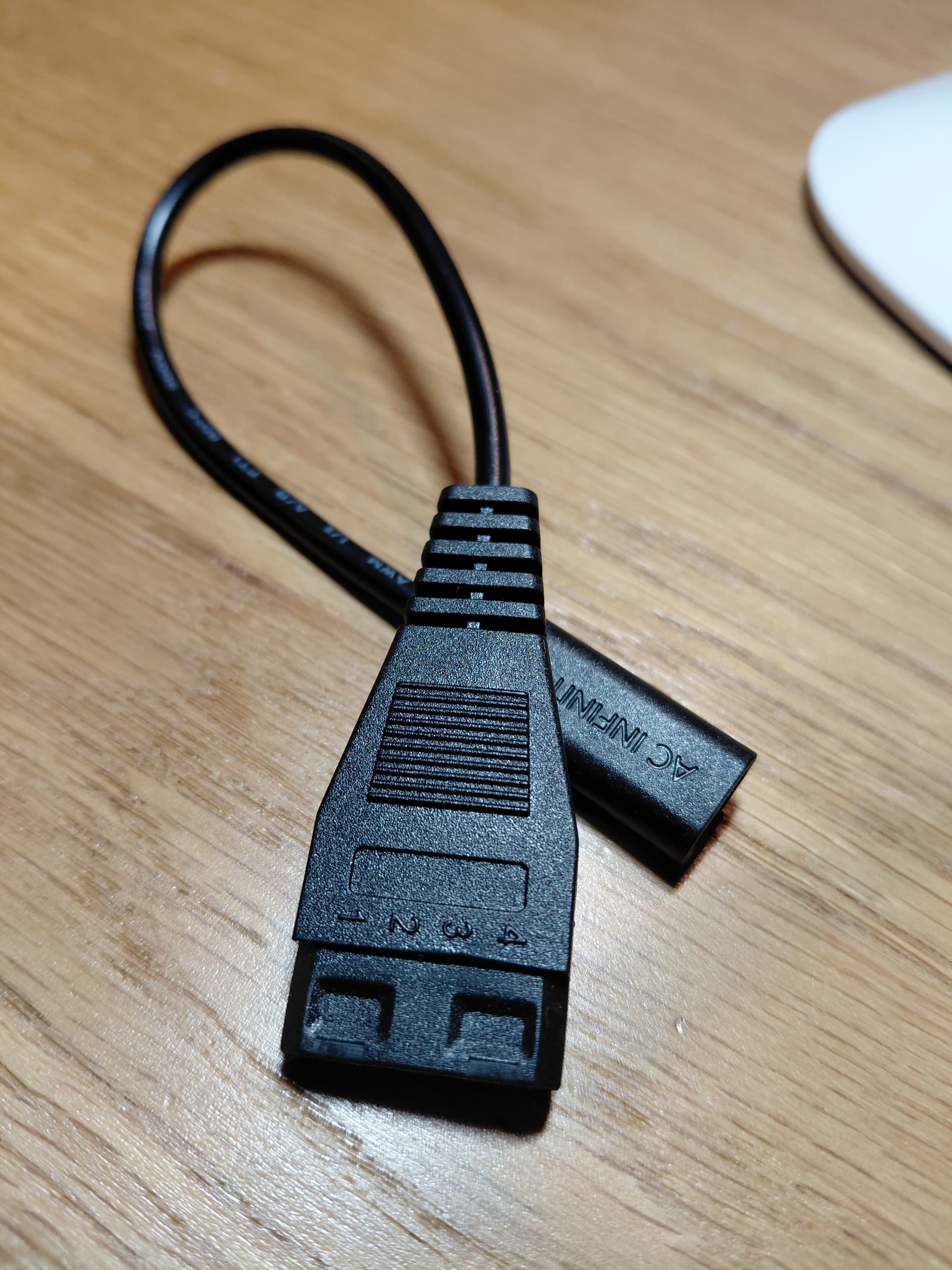
I have connected the fan to the speed control board using the UIS to Molex adapter included with the fan (pin 1 on the molex to pin 1 of the 10v end of the speed control board, pin 2 to pin 2, etc.).
On the 3.3v end of the speed control board I have made the following connections to the RPi:
3.3v pin to RPI GPIO 3.3v;
Ground pin to RPI Ground pin;
PWM pin to RPi GPIO 12; and
Tach pin to RPi GPIO 18;
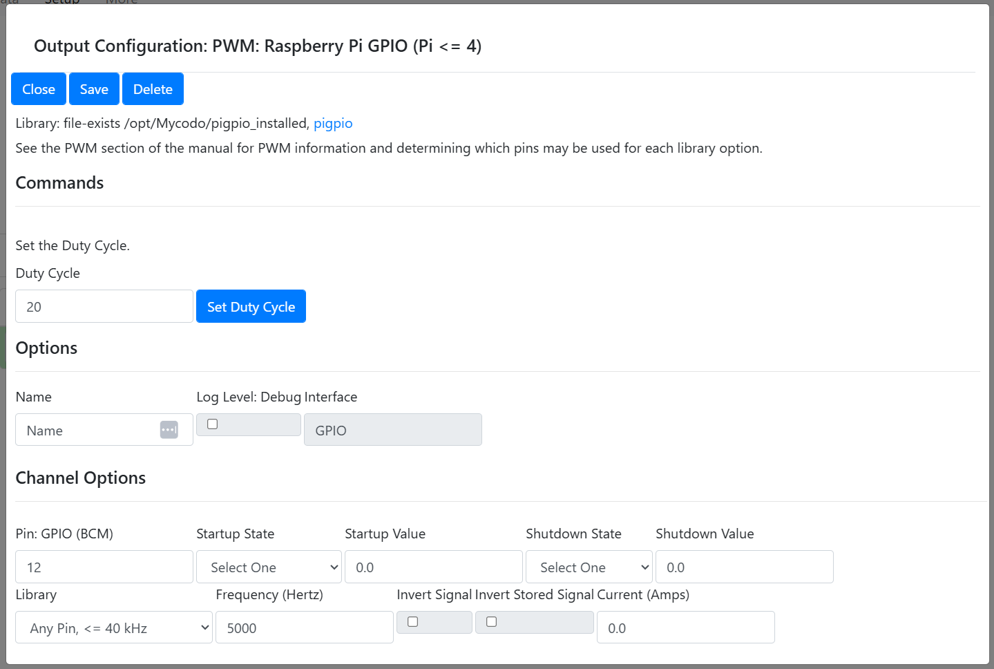
I have created a Mycodo Output Configuration: PWM: Raspberry Pi GPIO (Pi <= 4). I have set the Pin: GPIO (BCM): to 12. When I set the duty cycle to 10, 50 or 0, the fan speed does not change. The fan stays on and does not change speed.
Here is the relative extract from the log:
2025-09-21 19:01:14,801 - INFO - mycodo.outputs.pwm_gpio_ddd4806c - Output setup on Any pin 12 at 22000 Hertz
2025-09-21 19:01:14,801 - INFO - mycodo.outputs.pwm_gpio_ddd4806c - Initialized in 293.9 ms
2025-09-21 19:01:16,135 - DEBUG - mycodo.outputs.pwm_gpio_ddd4806c - output_on_off(on, 0, pwm, 50.0, 0.0, True)
2025-09-21 19:01:16,146 - DEBUG - mycodo.outputs.pwm_gpio_ddd4806c - Duty cycle set to 50.00 %
I have read the following posts here, here, and here.
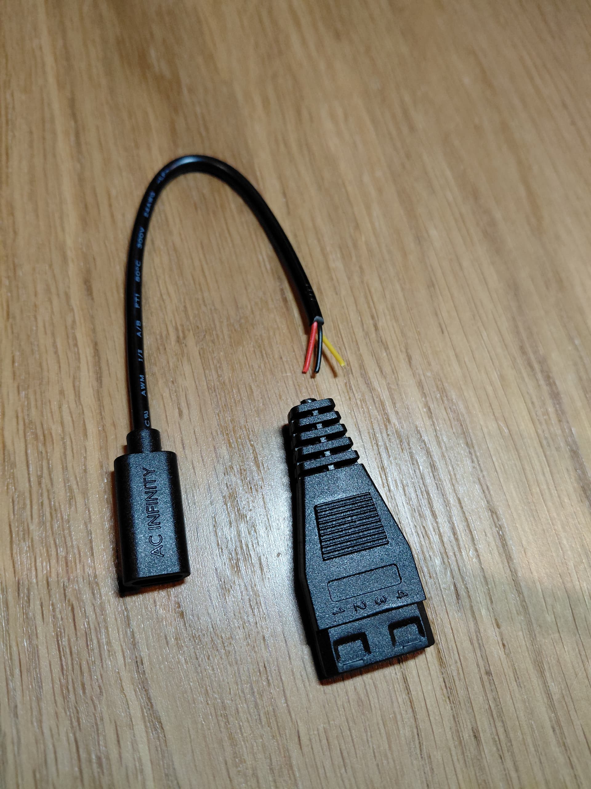
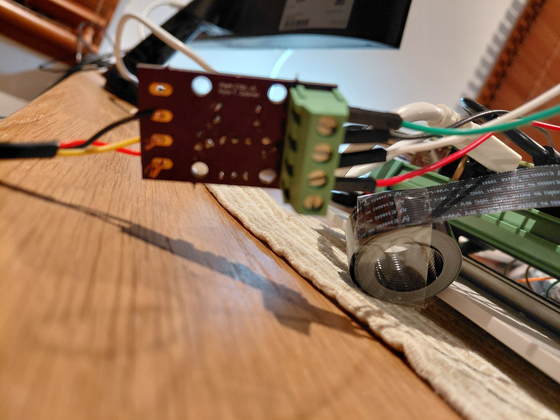
This leaves three exposed wires - red yellow and black which are assigned to Kyle’s speed control board as follows (no connection is made to the Tach - Pin 1):
Red: Pin 4 - 10V DC power;
Yellow: Pin 3 - PWM; and
Black: Pin 2 - Ground.
I have temporarily rigged the red yellow and black wires to test Kyle’s speed control board as I don’t have any 4 pin screw terminals handy.
On the 3.3v end of the speed control board I have made the following connections to the RPi:
3.3v pin to RPI GPIO 3.3v;
Ground pin to RPI Ground pin; and
PWM pin to RPi GPIO 12.
Note: there is no connection between the Tach pin on the 3.3v end of Kyle’s speed control board and the RPi GPIO. The photos above shows it connected, but I removed the connection after I took the photos.
Lastly, I have set up the Mycodo output using the PWM: Raspberry Pi GPIO (Pi <= 4) (pigpio). I assigned the Pin GPIO (BCM) to 12 and altered the Frequency (Hertz) to 5000 as follows.
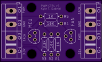
The photo you included of Kyle’s board shows the wiring to the UIS/Molex adaptor is not soldered. I assume the one you’re actually using is? Also make sure you have good solder joints on all components and no bridges (sorry, just stating the obvious).
I’ve been working on creating different PWM boards, based on Kyle’s, for easier use with the USB-C cables found on the AC Infinity and Vivosun (crap) fans but haven’t completed testing them yet for any mistakes (I did use the wrong footprint for the transistors, making them really difficult to solder without bridges). I’ll supply links to the Gerber files here on the forum when I have completed testing and documentation. I also have a board for ESP32/MQTT fan control, powered by the fan, I’ll be releasing.
Also, incidentally, I’m finding 12000 Hz seems to be the sweet spot on the AC Infinity fans I’ve used. YMMV
There are some transistors in the TO-92 style that use a different pin layout than the 2N3904 and this has caused some issues when soldering (including myself, when I used different transistors for a board I made), since you can’t just align the part with the printed layout on the circuit board and have the pins match where they’re supposed to be soldered, if the pin layout is different.
At this point, you’re going to need to test the circuit. You’ll need to first determine if you’re generating a 3.3 VDC PWM signal from your Pi, then check the circuit on the board at every component to verify the proper functionality, to determine why there’s no 10 VDC PWM output.